


Introduction
Well thanks for reading so far... haha...
As a few of you may know, I've had and done a good few seicento conversions in the past and was intending to do my mk2 c20xe (Vauxhall 2ltr) but this time around converting it to turbo (low boost).... Anyhow... As with most things in life, circumstances changed and buying a house took over, so this project sadly seen the bin!
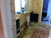
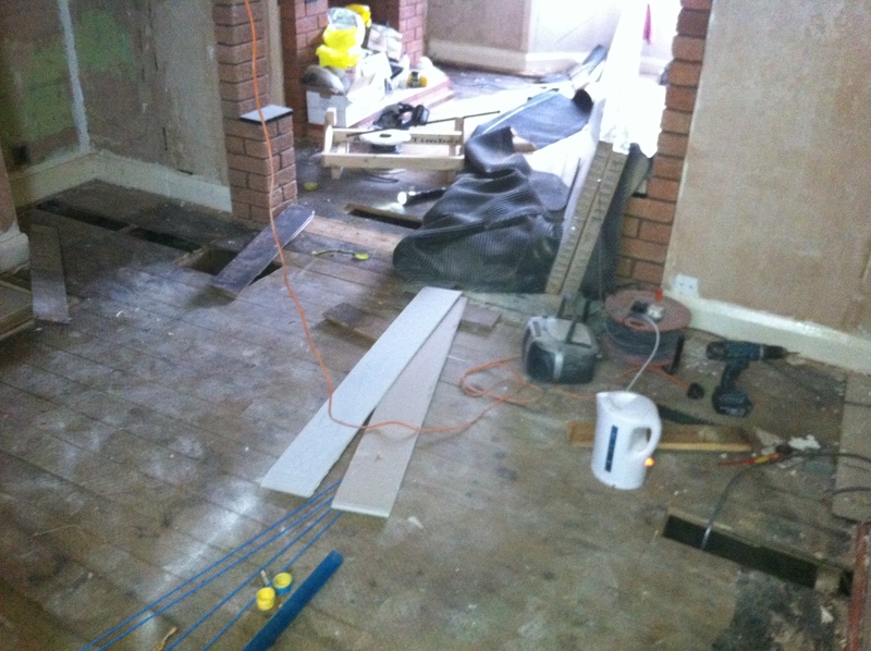
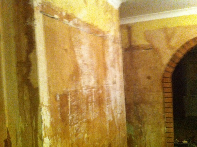
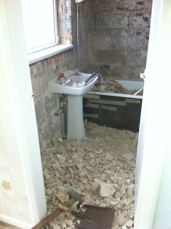
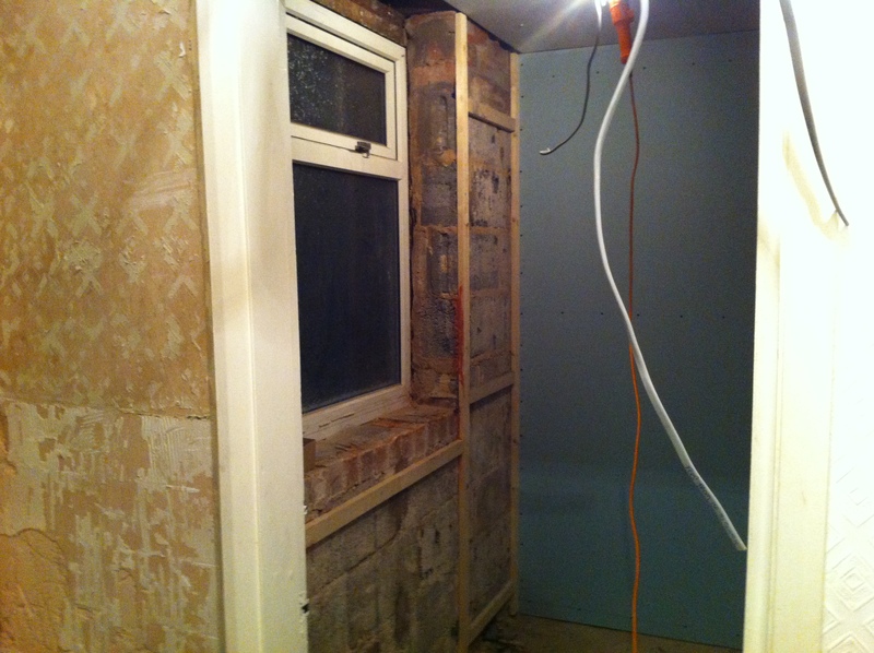
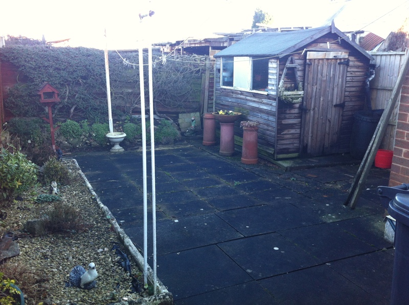
The house took up a massive part of the year, as it needed fully renovating to bring it up to scratch, including rewiring, plastering new kitchen and so fourth... Due to me being self employed as an electrician/plumber, I ended up taking 3 months off work and doing the lot myself....
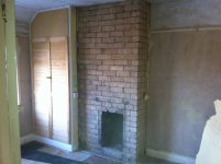
3 months later it went from this....


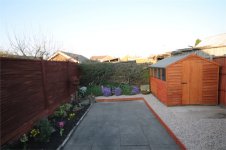
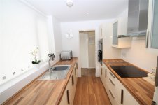
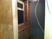
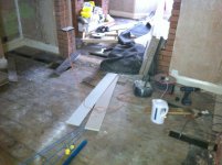
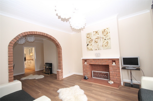
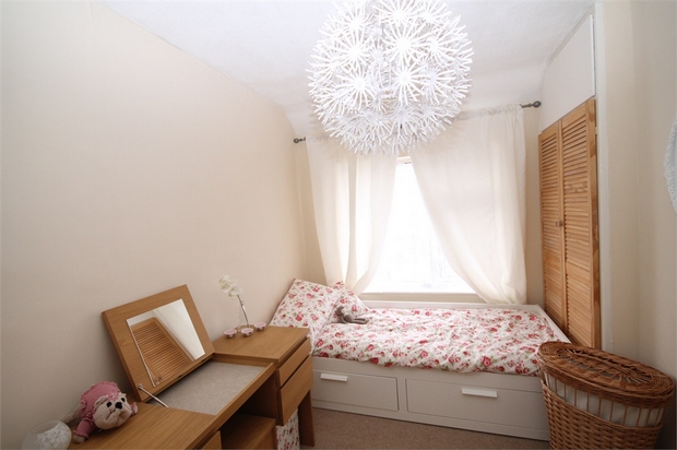
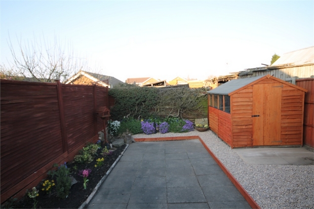
To this....


We got the keys originally in January this year, and now things have changed yet again as we have just accepted an offer on the house, and currently going through the sale process for it lol!!
However it now means the house we have put an offer on is much newer, requires hardly any work and the best bit.... I finally have a GARAGE This is a first for me as im usually found outside in the rain and snow working on my cars....
So now you know why I have been soo quiet, and why my last project was thrown to one side!!
Anyhow, onto the car!! Ive been secretly waiting for my old 1.4 seicento turbo to come back online for sale, always joking that if it did then I would buy it to strip into parts as it had a fortune 'apparently' spent on it (think upwards of 18k)....
Very recently, I had a text off todger, with an ebay item number Thinking nothing of it i searched the number, and to my surprise the 1.4 seicento was on there for sale haha!! I rang todger and talked through whether or not it would be worthwhile to buy back, and we ended up making an offer to the guy for £650....
As the car had a gearbox problem (solidly stuck in gear), it needed to be trailered upto me from Kent to Warwickshire for the grand sum of £135....
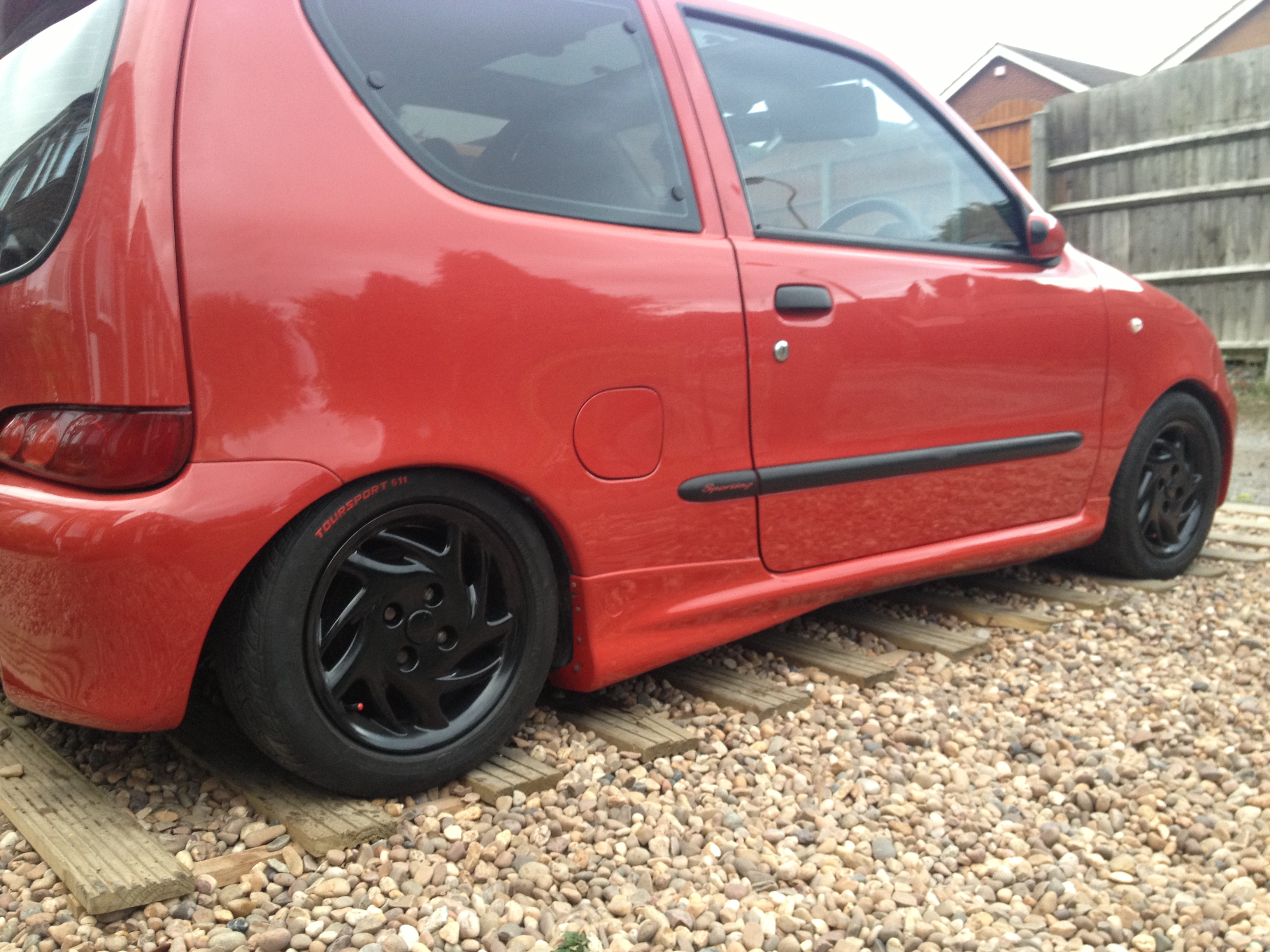
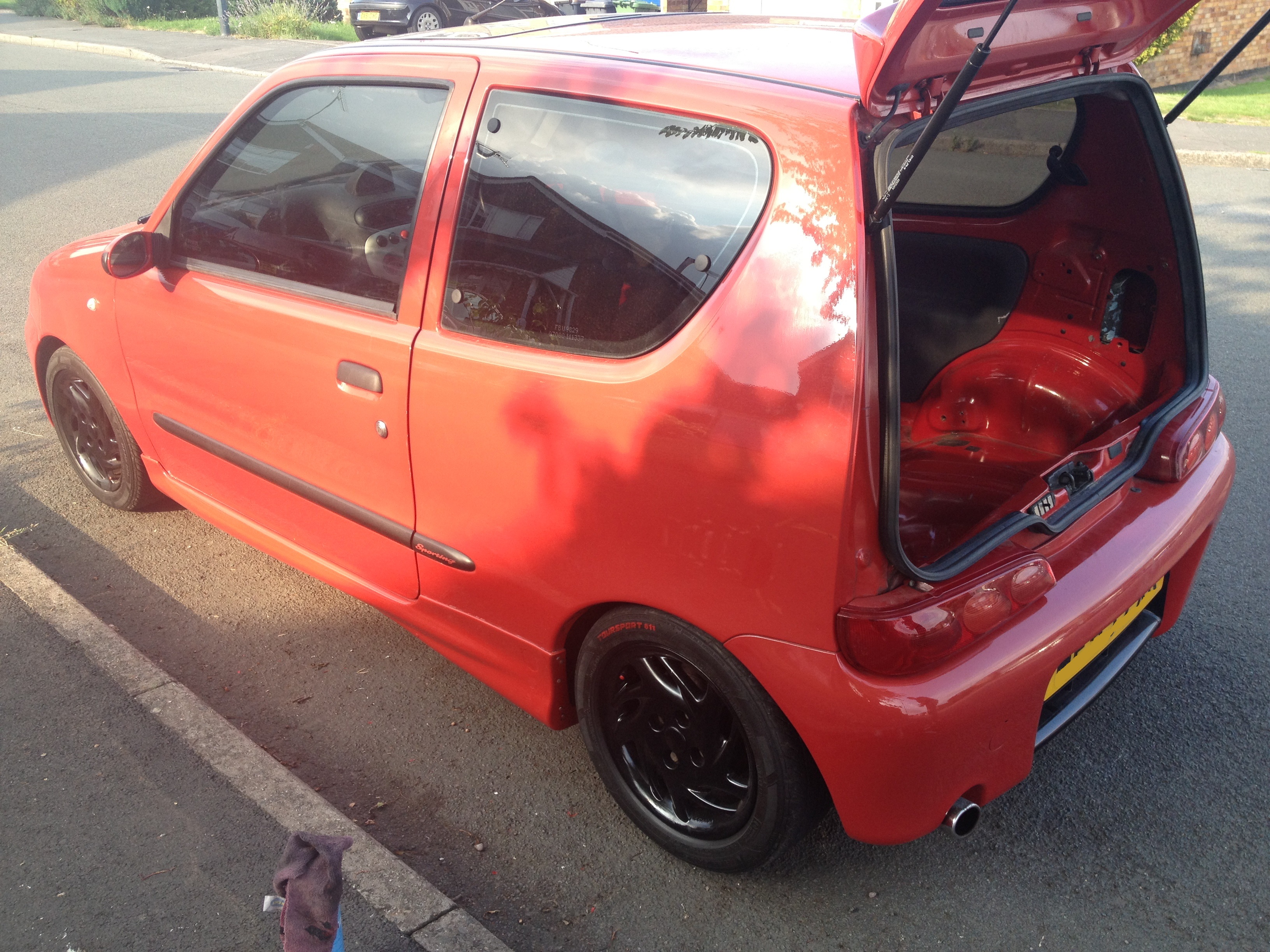
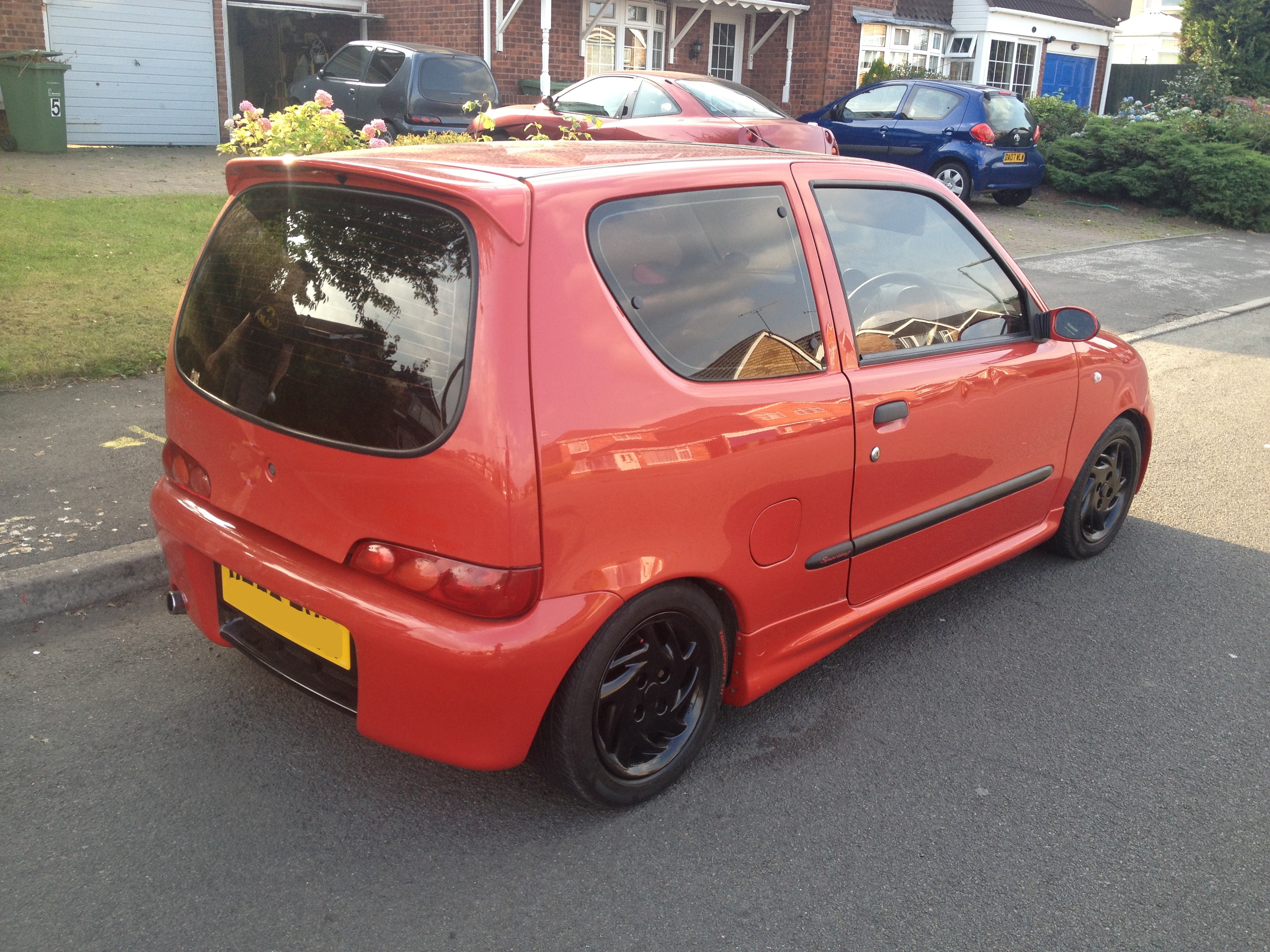
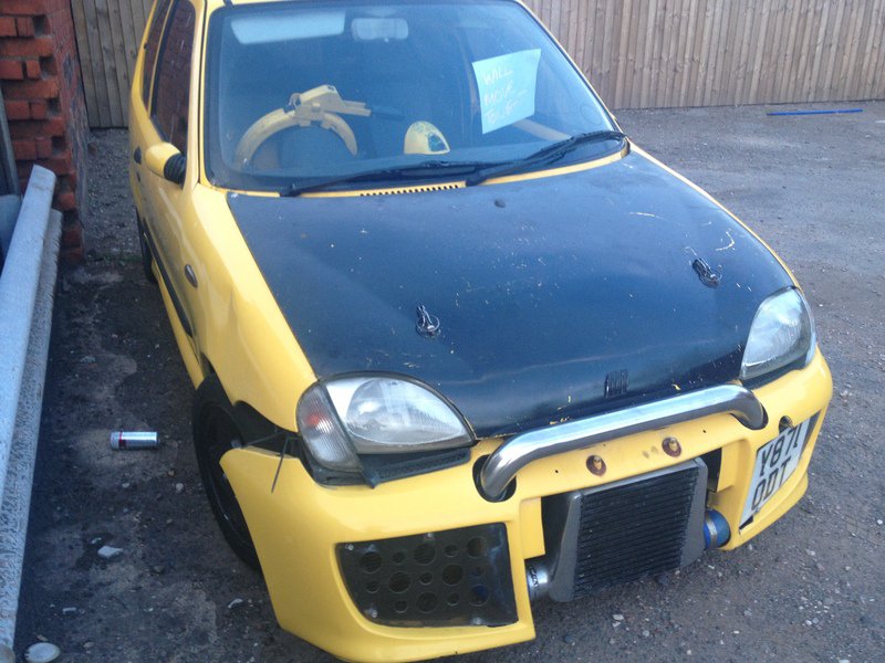
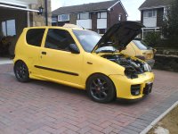
Anyhow, it arrived, and to be fair I had forgot how bad it looked.... what an eyesore..

As much as it looked bad when I owned it the last time, it has got progressively worse!... Its well known on the forum as a bit of a sl*g car due to the amount of owners it has had in its life....
It was apparently built by Wardy25 and his friend, with wardy paying for most of the work. From what I gather, there was a dispute of some sort between the two, and the car was never fully finished.. As you can see it wasn't mint, but it never used to look quite so bad...

No idea how its got into the state that its in now lol, but its time for me to change that!!
The original car is way too gone to save, and to be fair as I point out later, the engine conversion itself hasn't originally been carried out too great... Such things as the main engine mount being welded to the thin bay metalwork, and not to anything structural resulting in the mount passing through the bodywork... How was this repaired?... with the aid of exhaust rubbers mashed in-between the body and engine supporting it in place lol.
Ive started stripping the car down.... and NOT to my surprise I've found loads of reasons why this car has never actually ran properly lol..
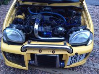
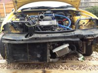
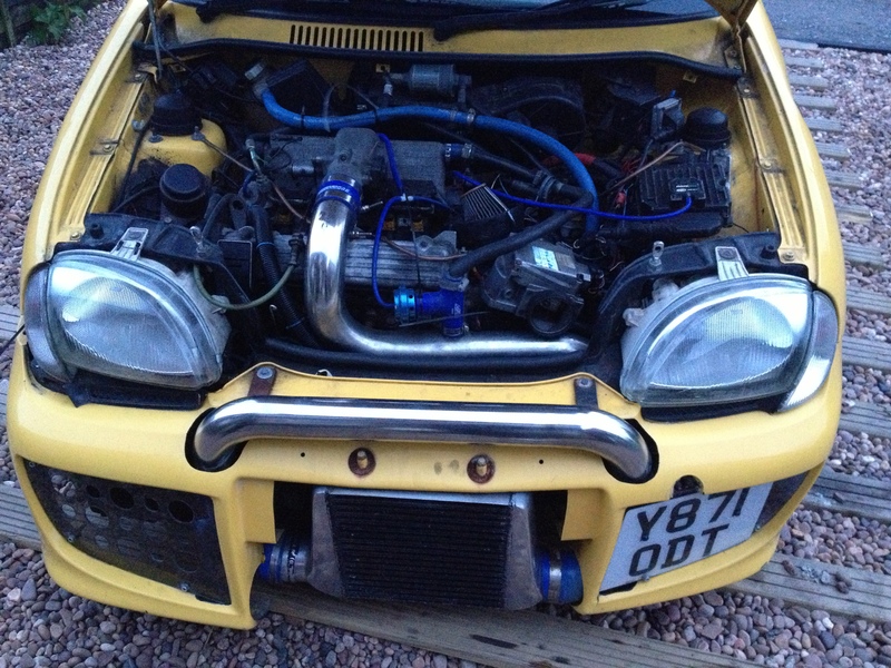
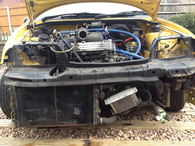
The engine bay... Upon inspection at this point, things just look messy, but nothing screams out at you...
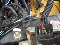
Then its time to uncover the electrics... (ignoring that the badly positioned stainless boost pipe work is arching out on the broken HT leads)..
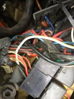
All this lot was hidden in a plastic box in the engine bay....
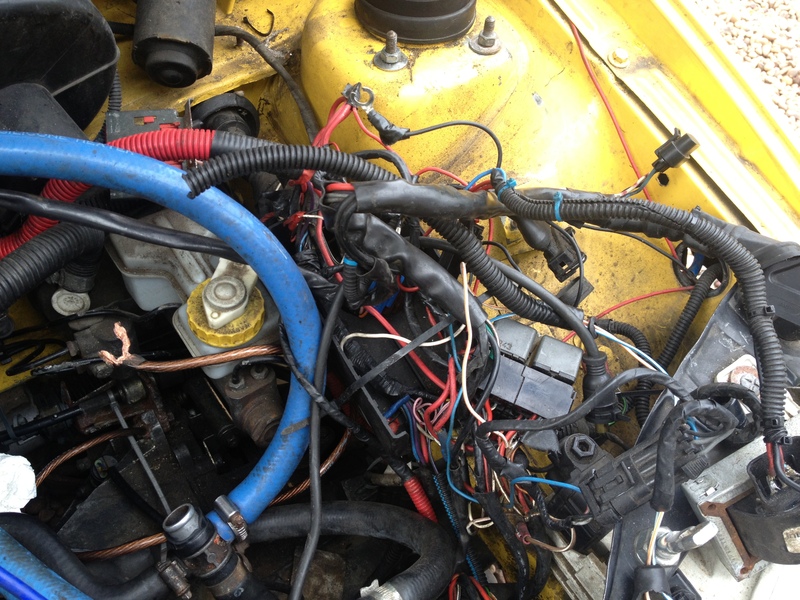
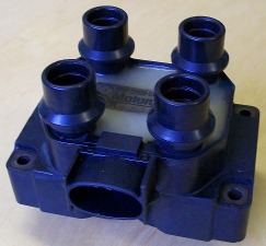
There are exposed connections all over the place in the engine loom, for example the coil... Soldiered, practically all pins touching...

Relays

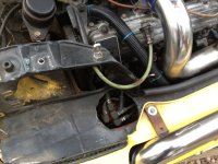
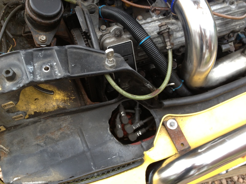
Dizzy slam panel mod... (as you can see the boost pipe runs across the HT leads, and with the friction it has worn through two leads creating obvious problems).
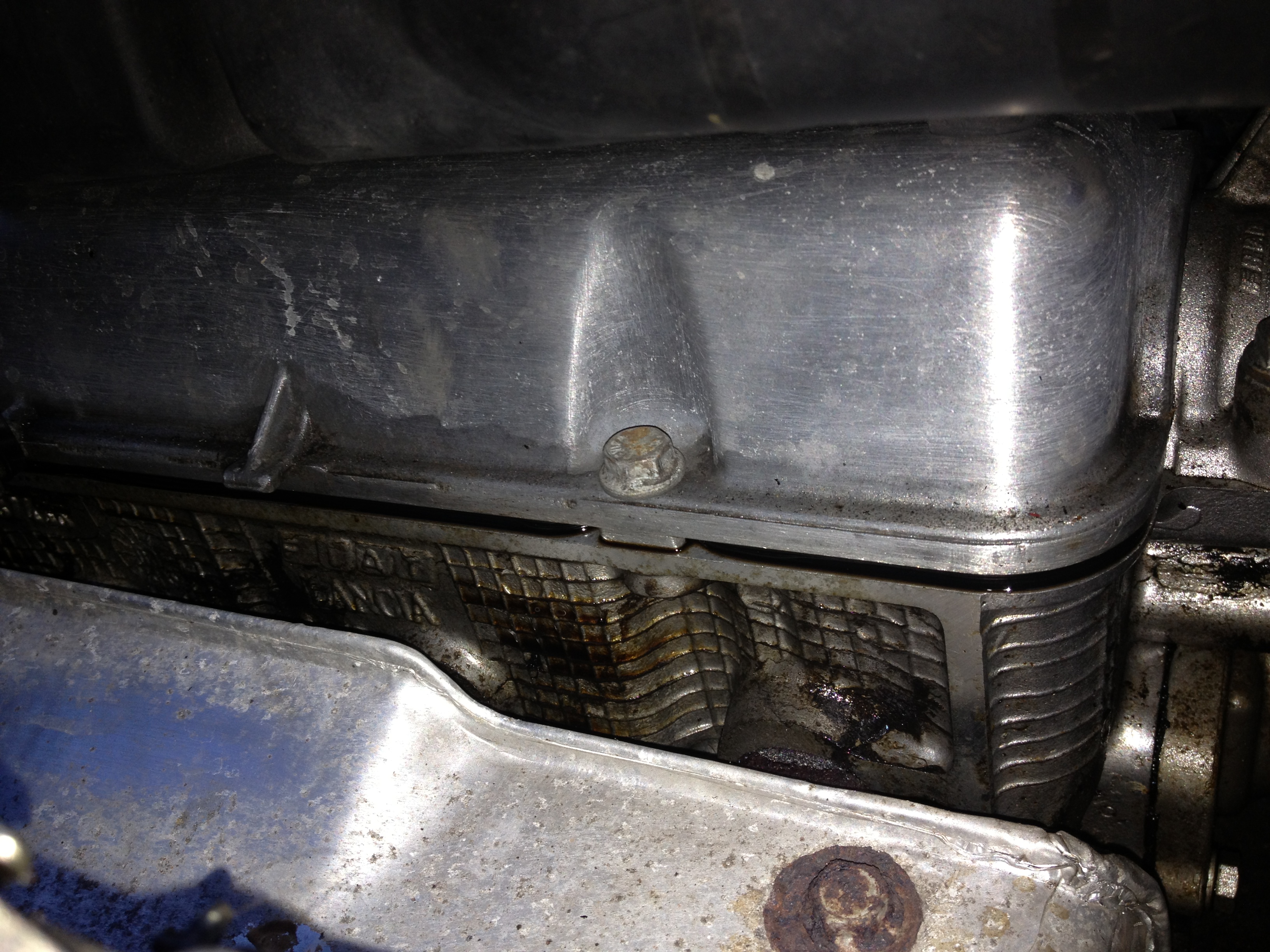
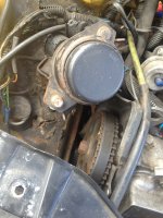
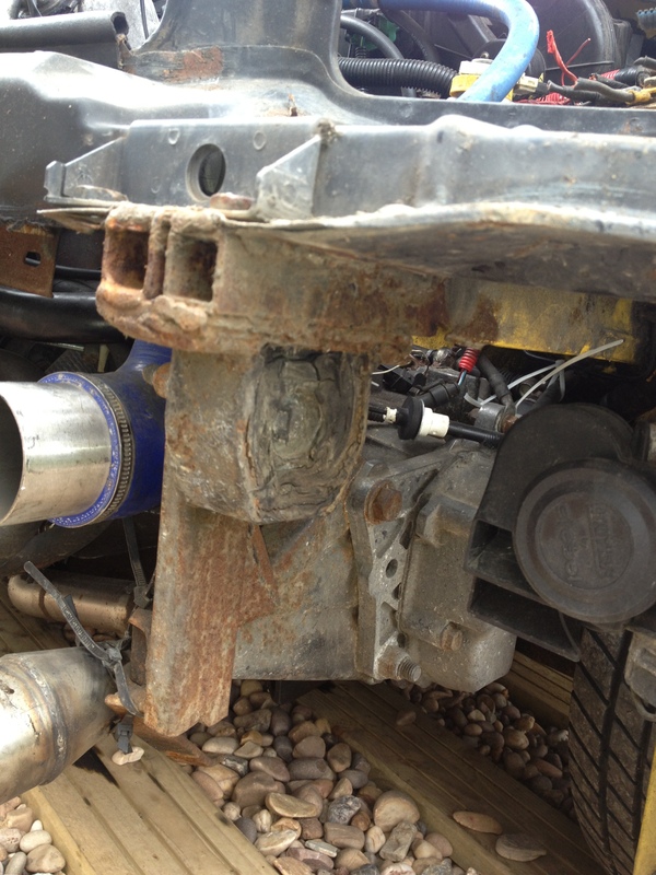
And then onto my favourite... The engine mounts....
With this beauty, it seems to have been welded to a single skin part of the car which has no under support as far as I can tell... The mount looks to have given way (well at least ripped the metal work apart)... and then fixed with perished exhaust rubbers... Im guessing by the look of the half width cambelt, the engine has dropped while running...


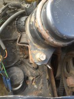
We then have this other 'custom' mount on the gearbox side.... (there is one to the rear, but I haven't got a pic yet... I will however as that's a beauty too)...
Other than the fact the wirings bad, the mounts are awful, its an eyesore, and the car is stuck in gear.. I think ive got a bargain... *rolls eyes*
The car is currently in this state, and im removing the salvageable parts off, to reclaim some money back and then put towards the rebuild & reshell...
I'm intending to...
*Fully strip the engine and rebuild
*Buy a replacement gearbox, or recondition the one I have
*Re-shell into a better donor car
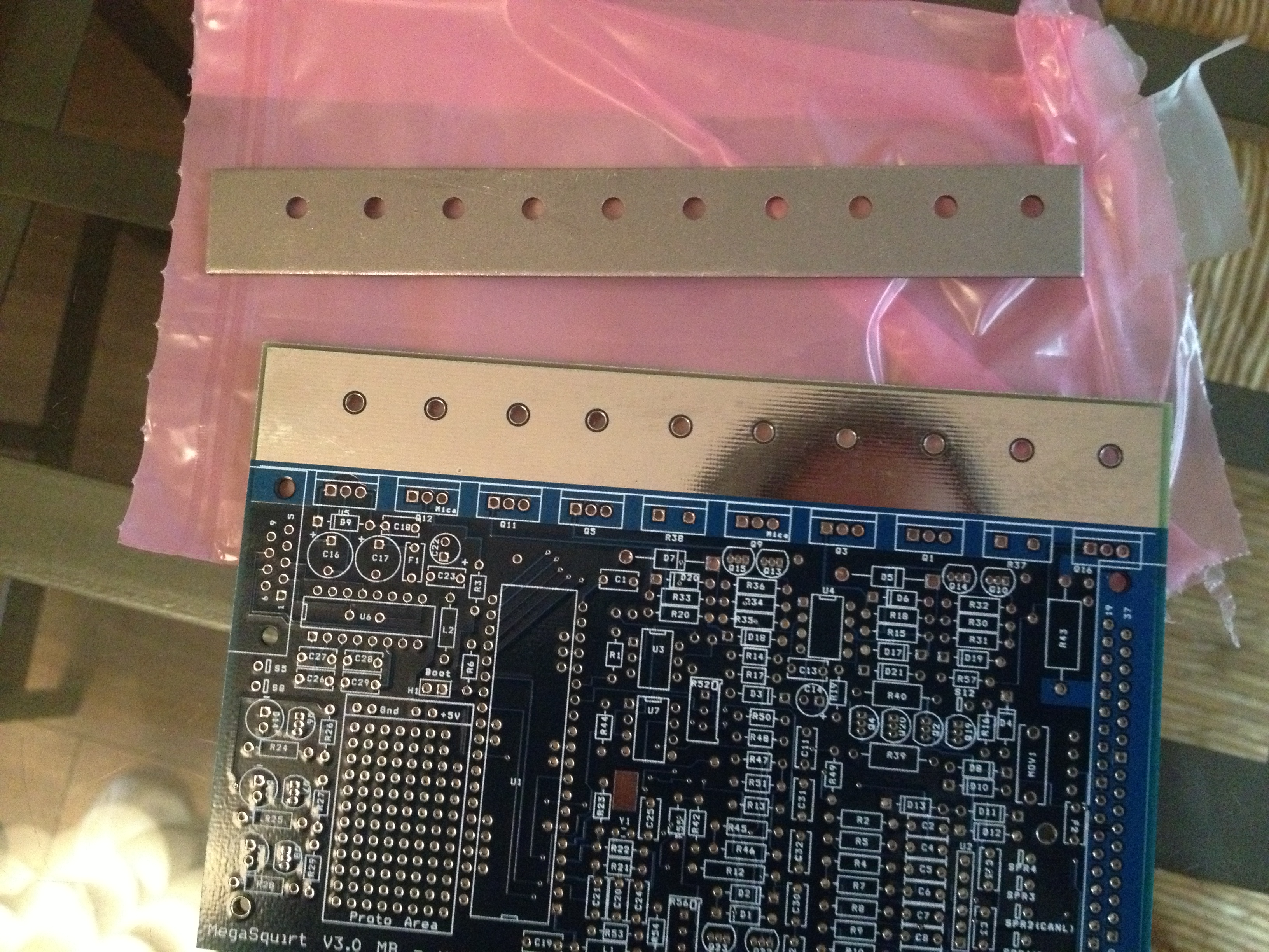
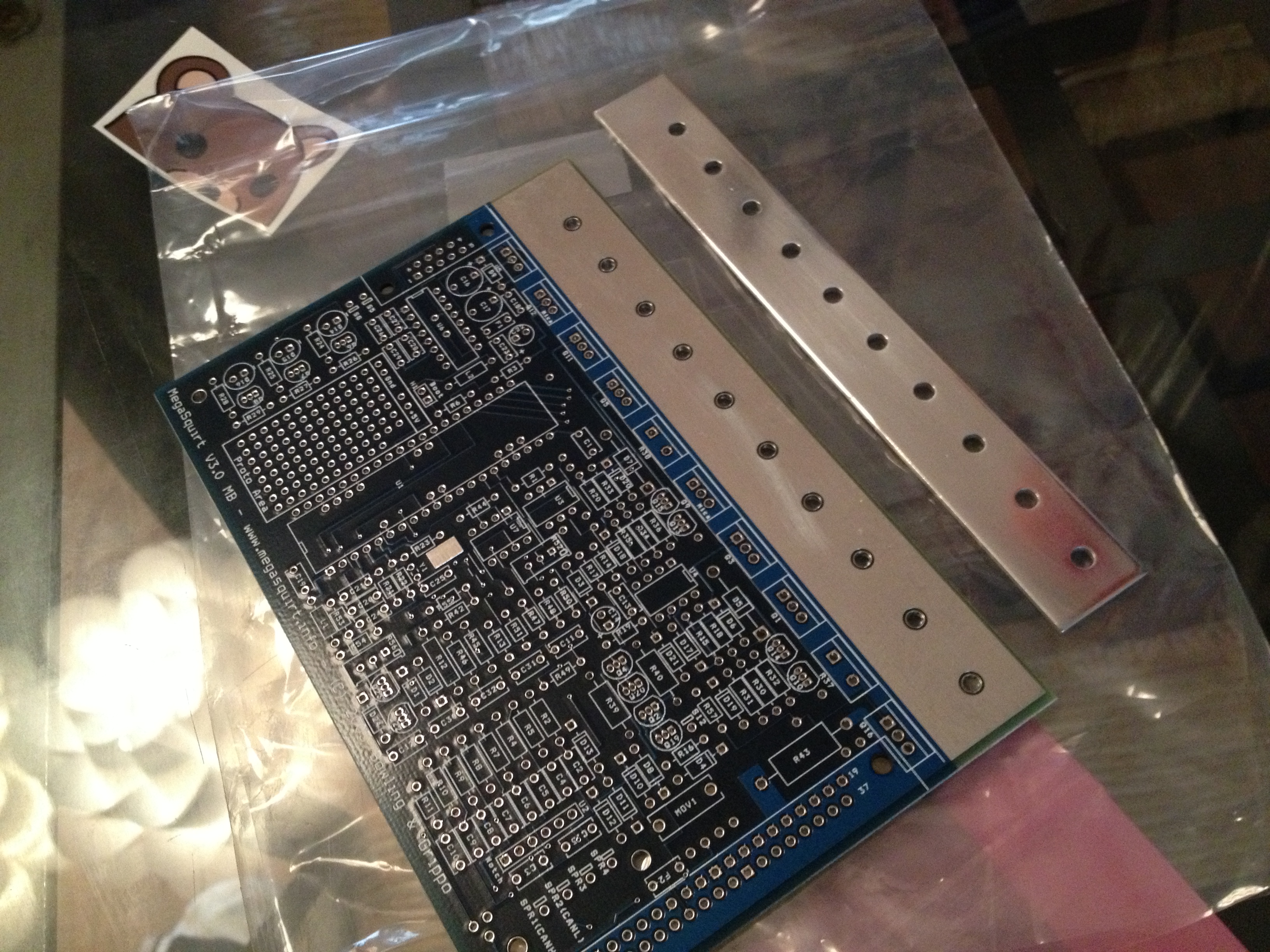
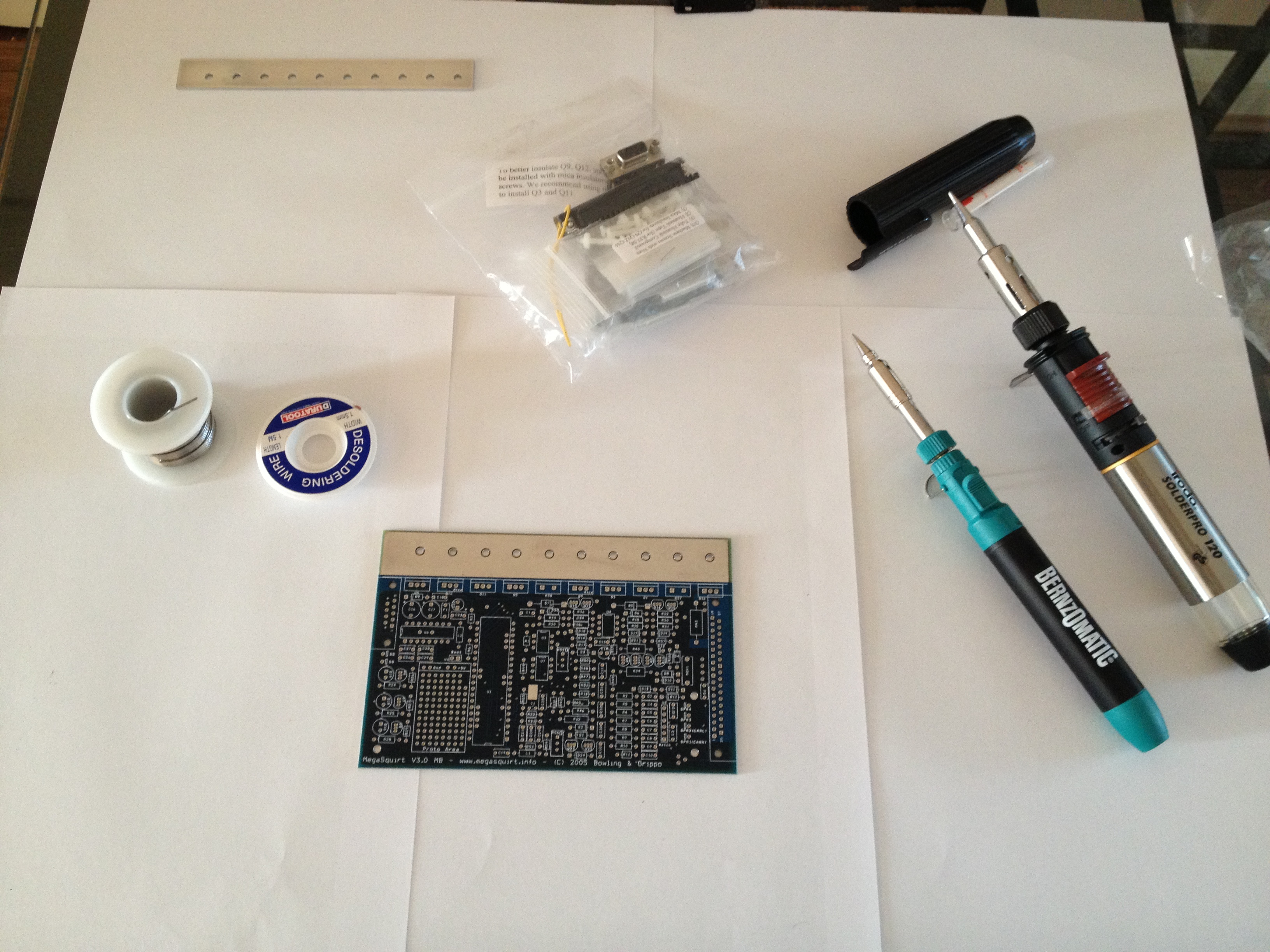
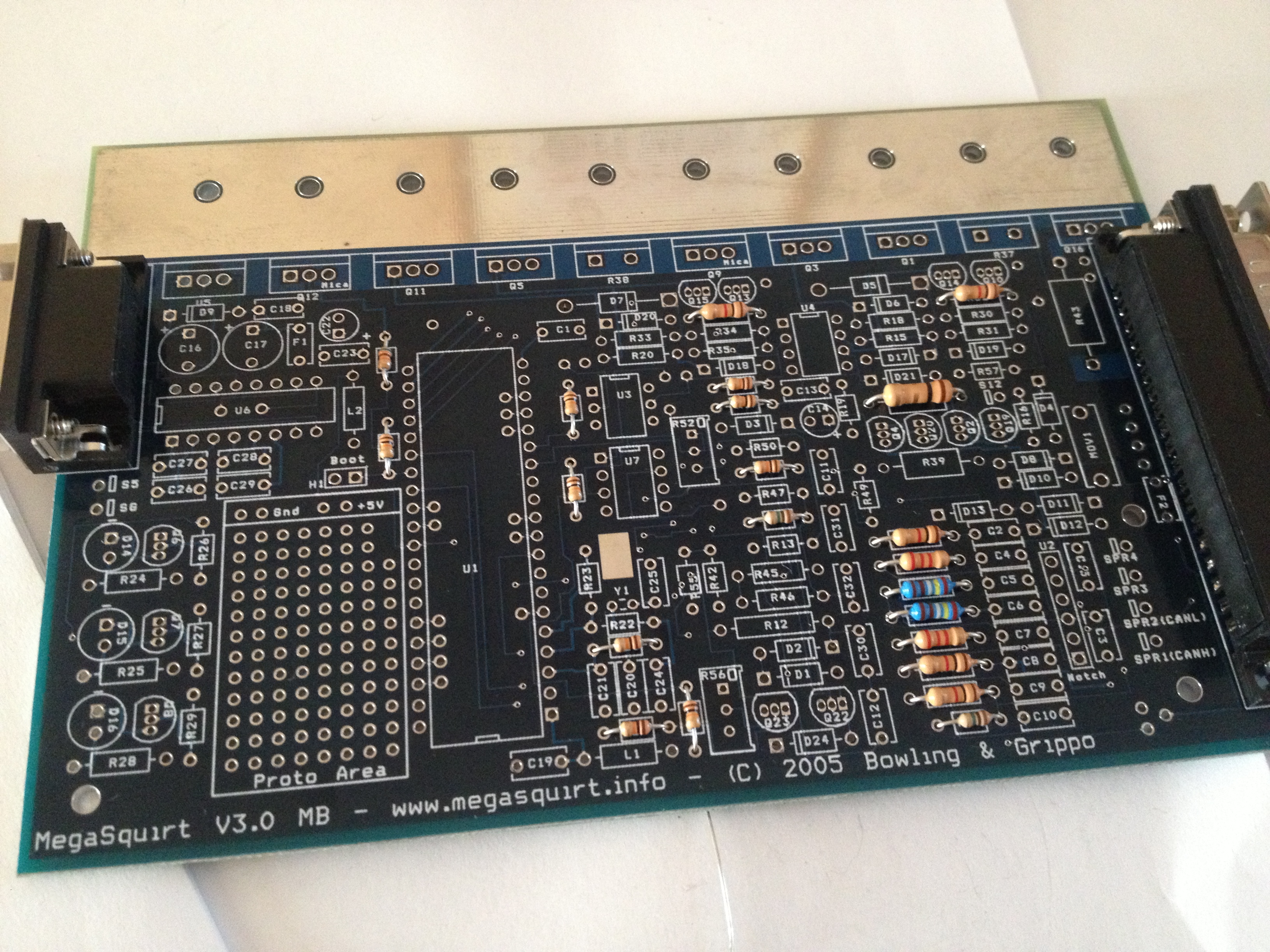
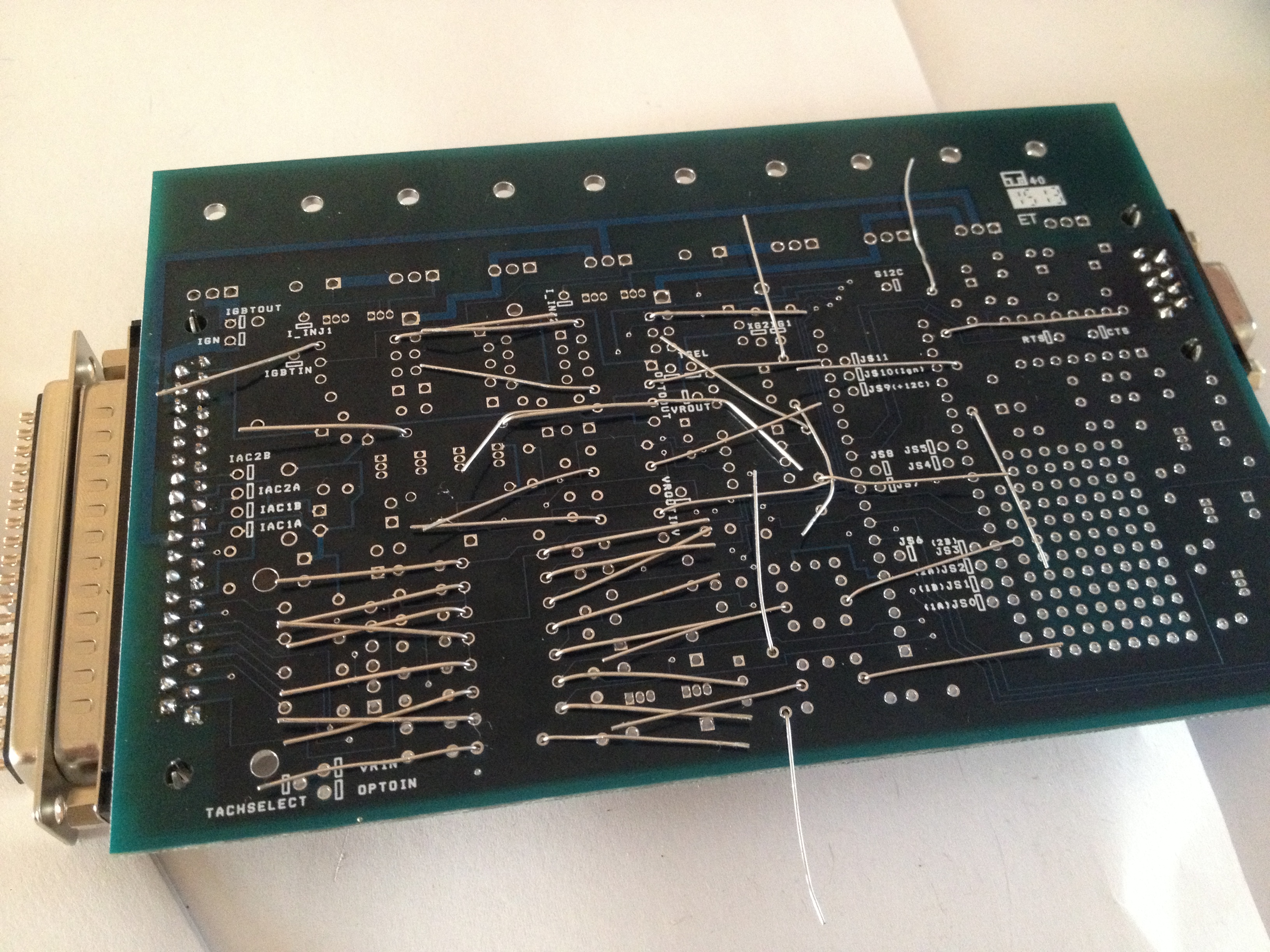
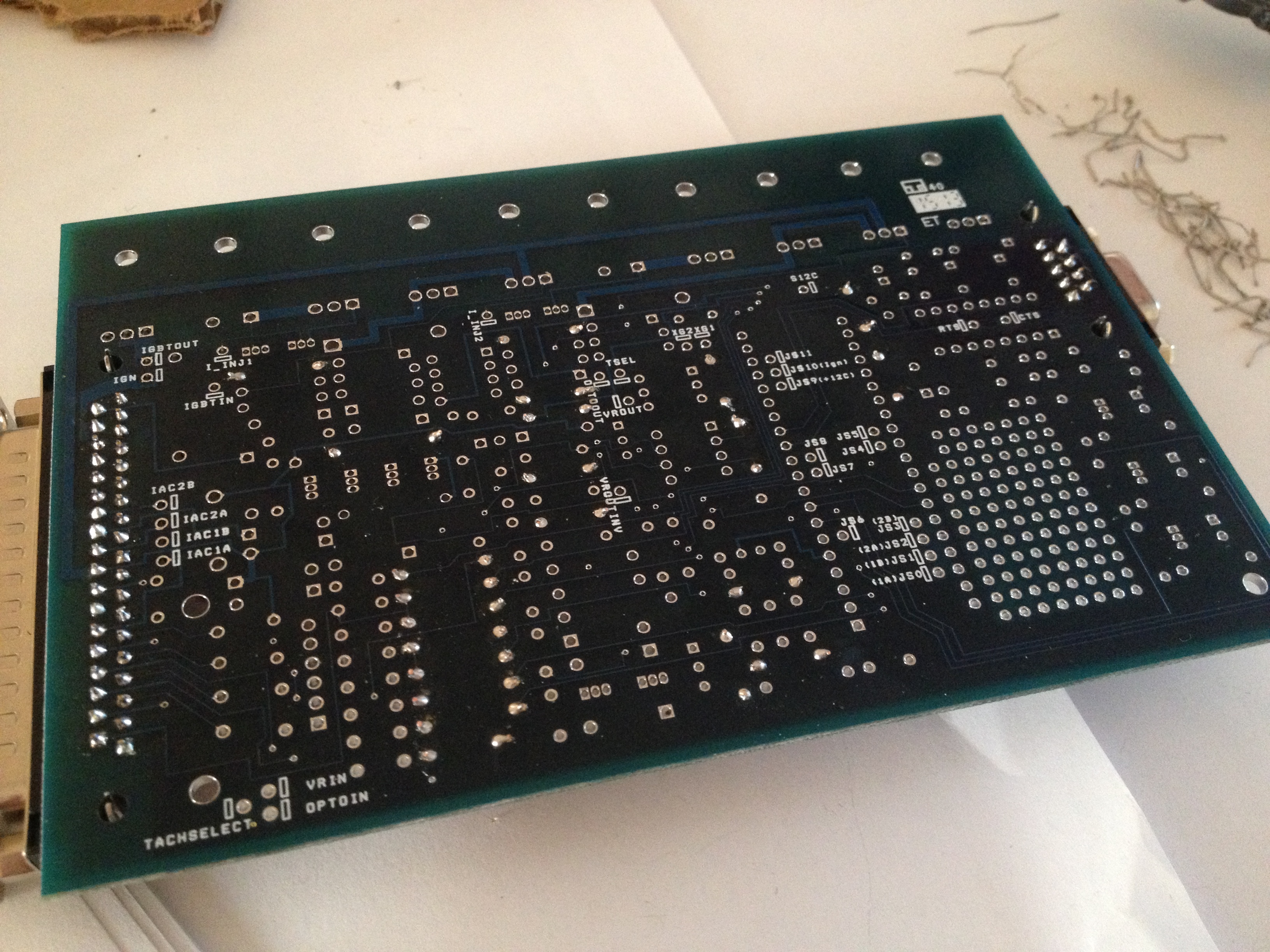
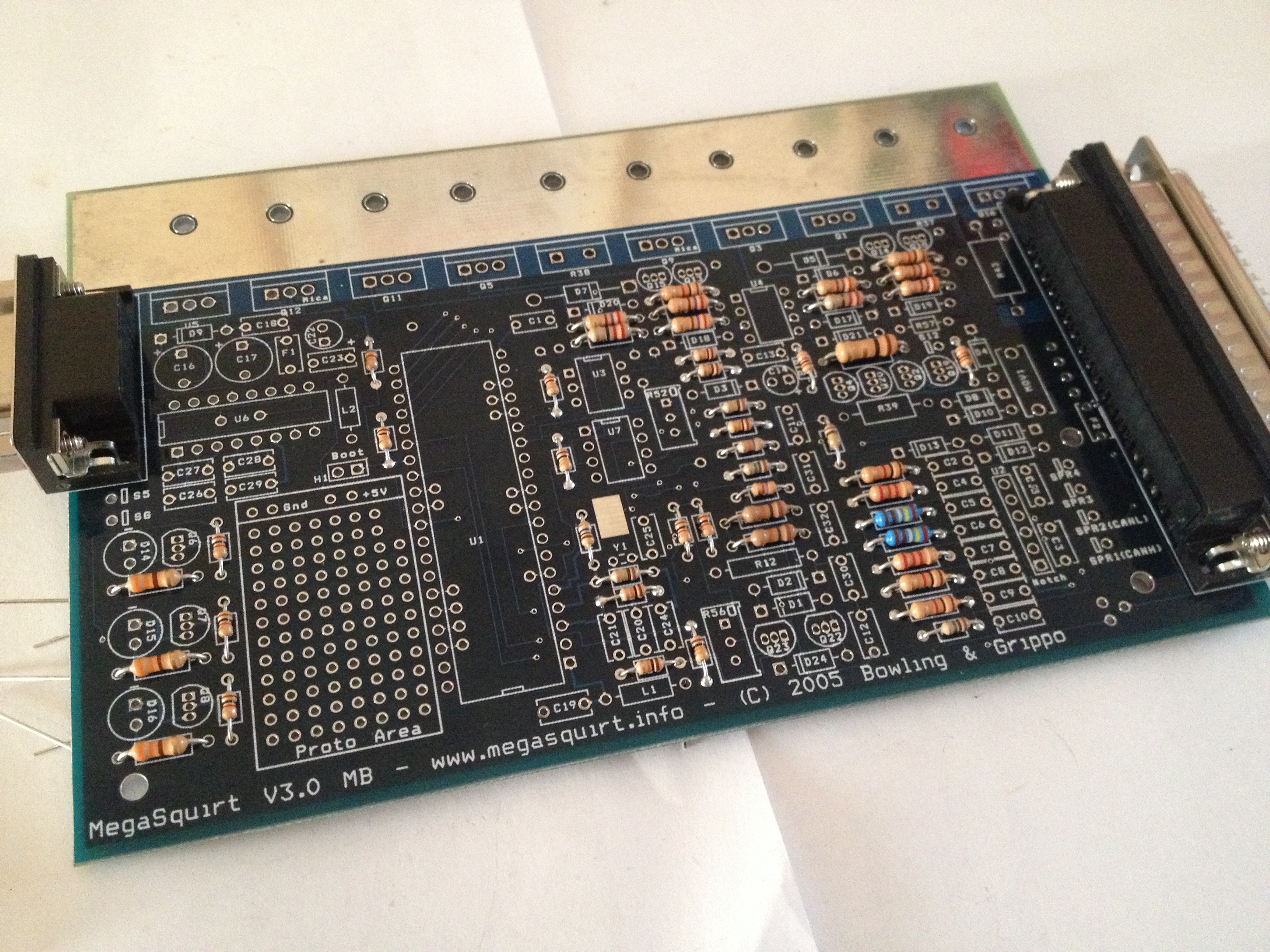
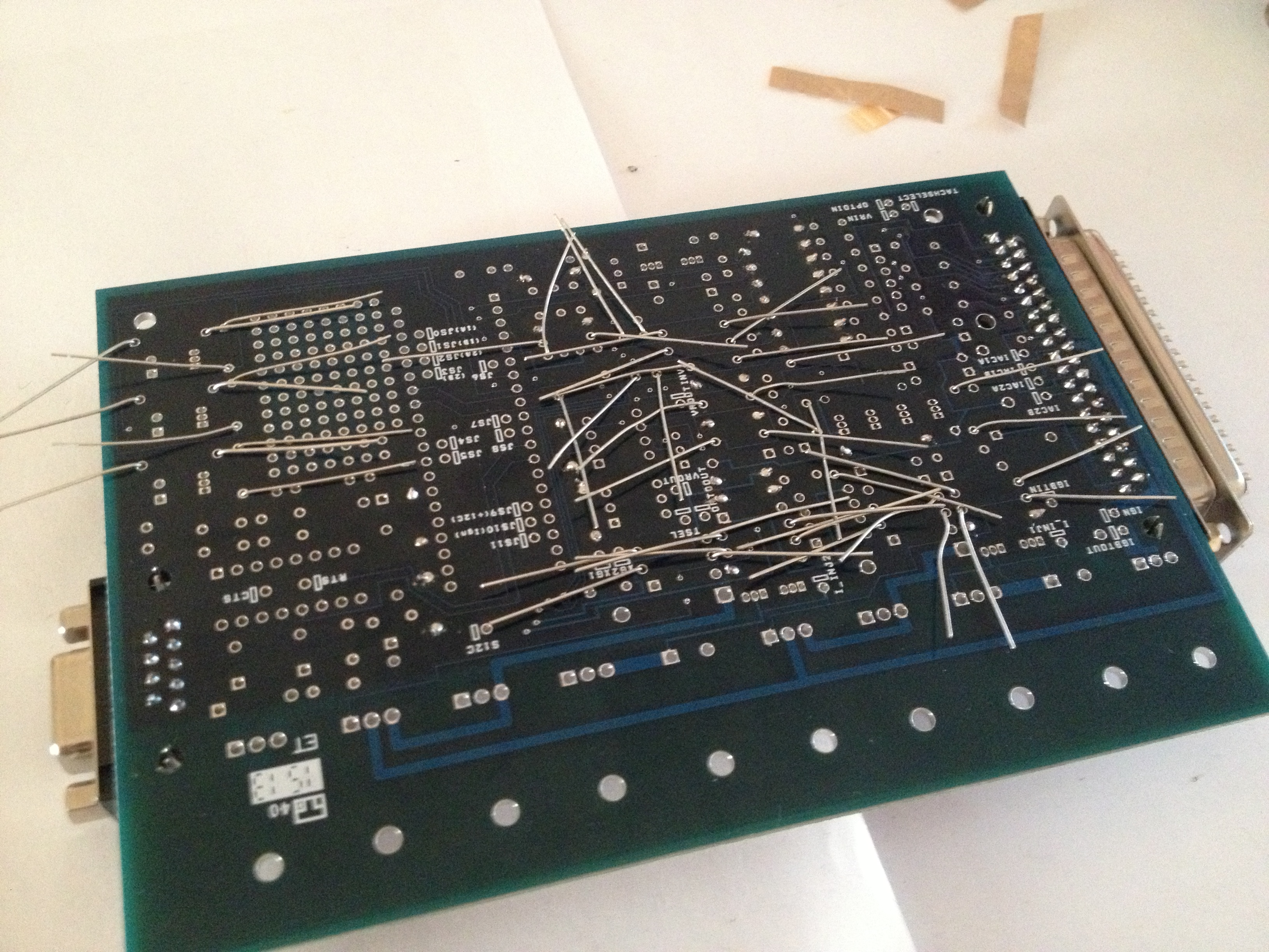
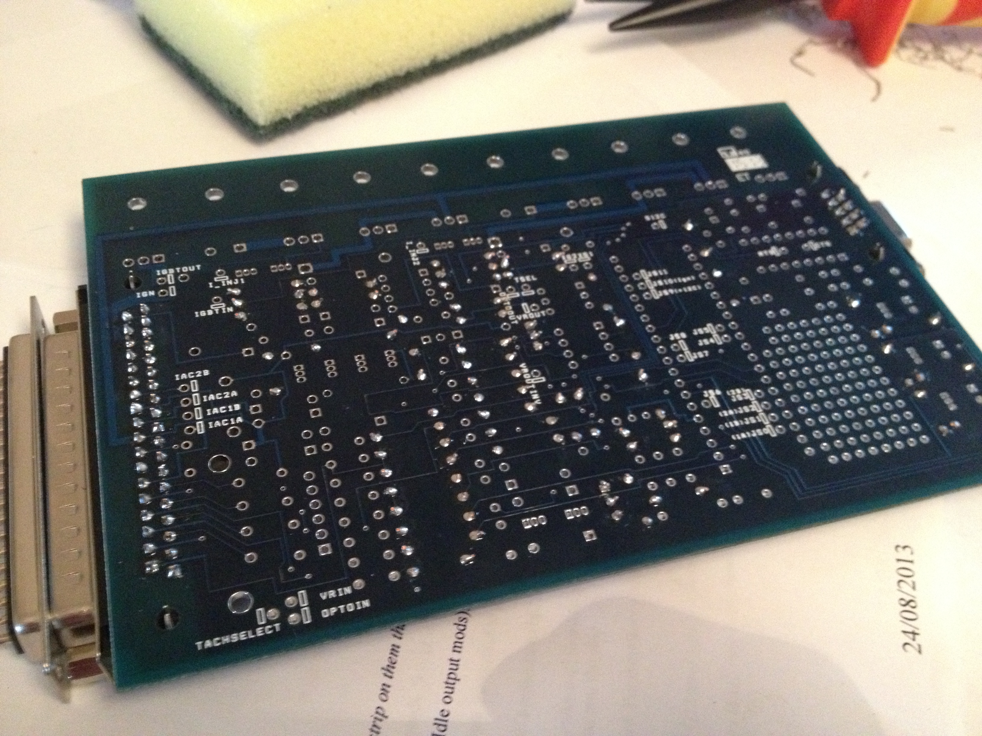
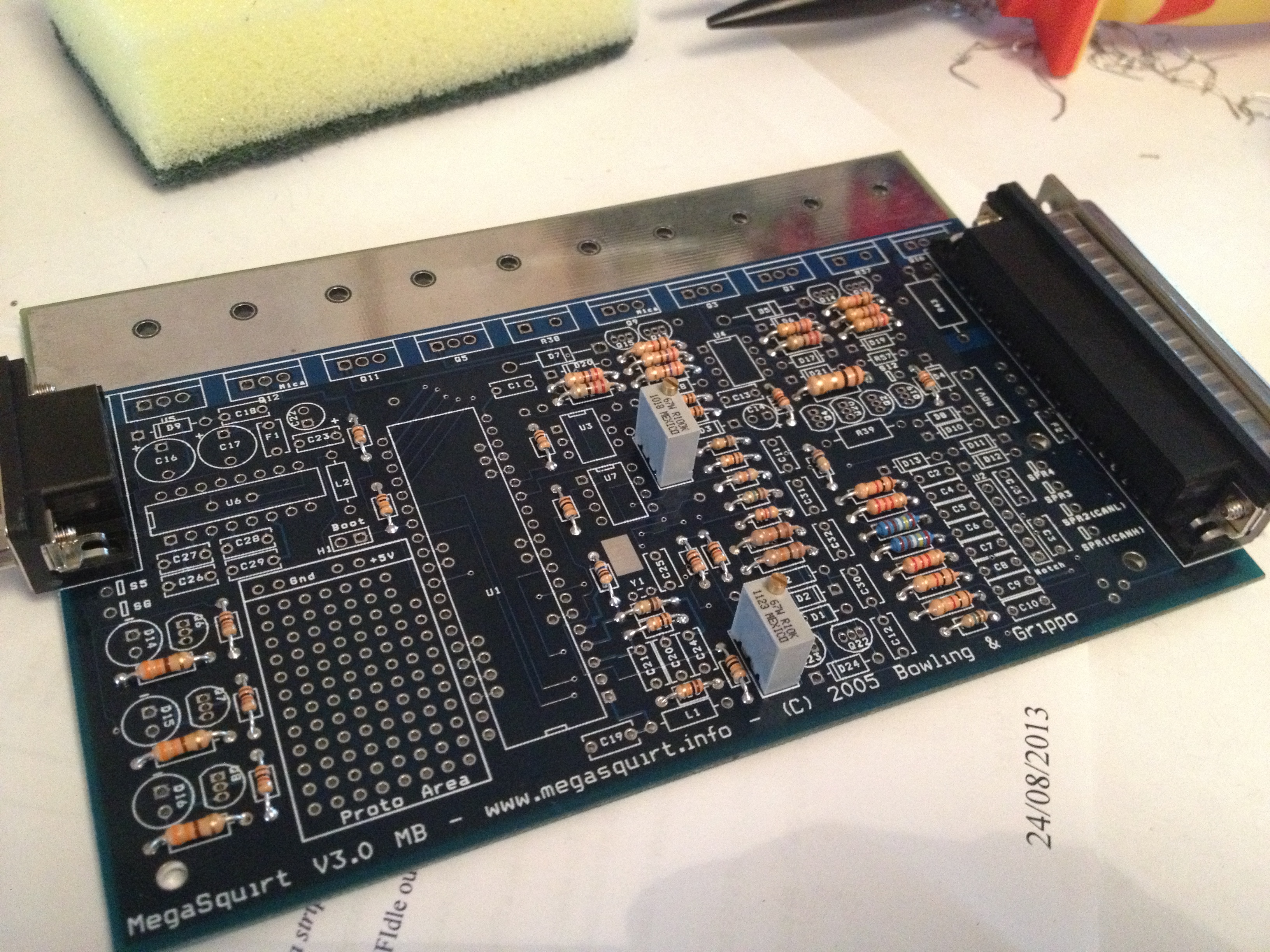
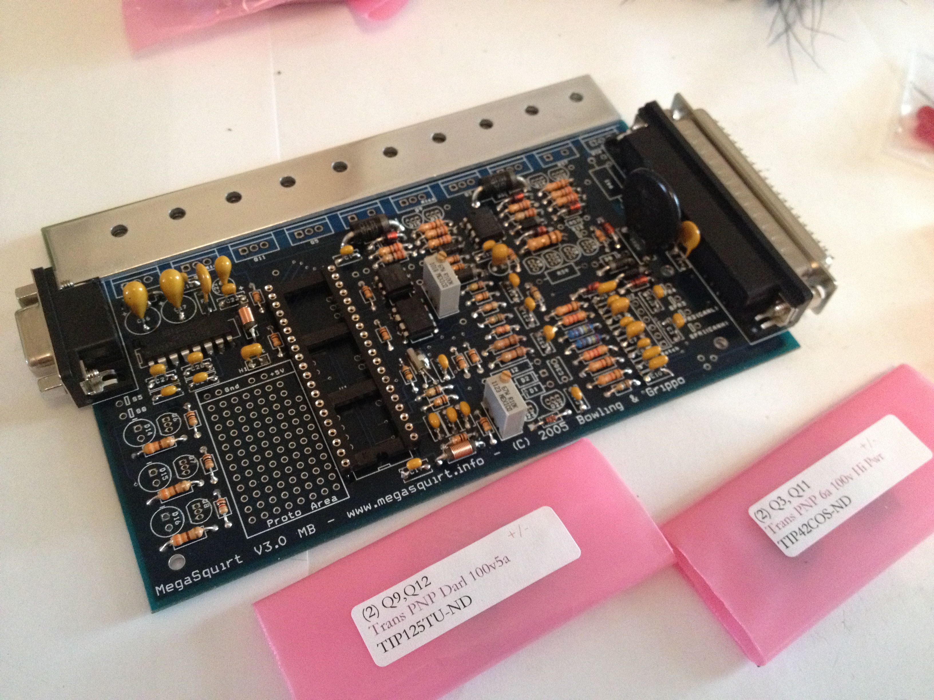
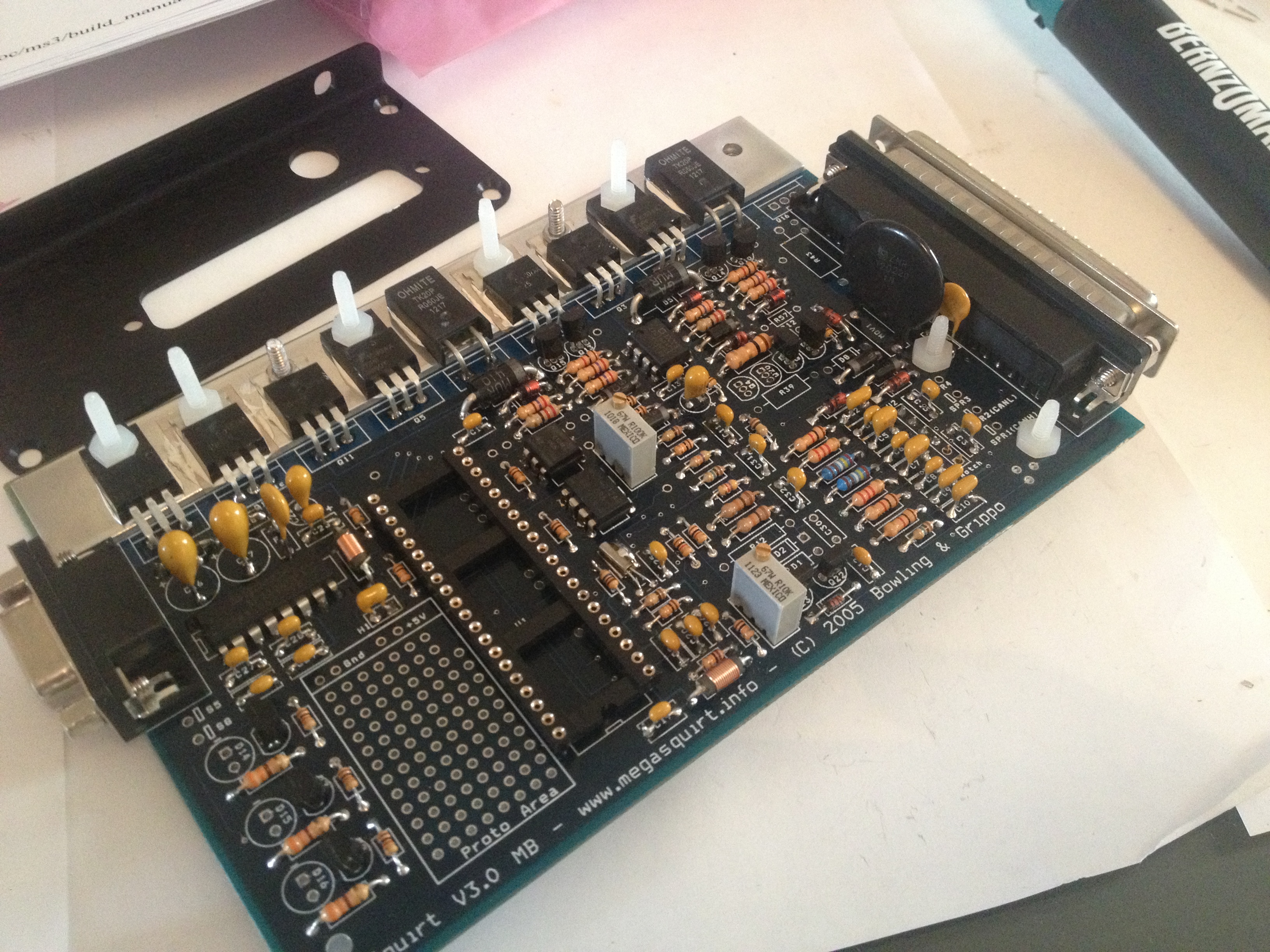
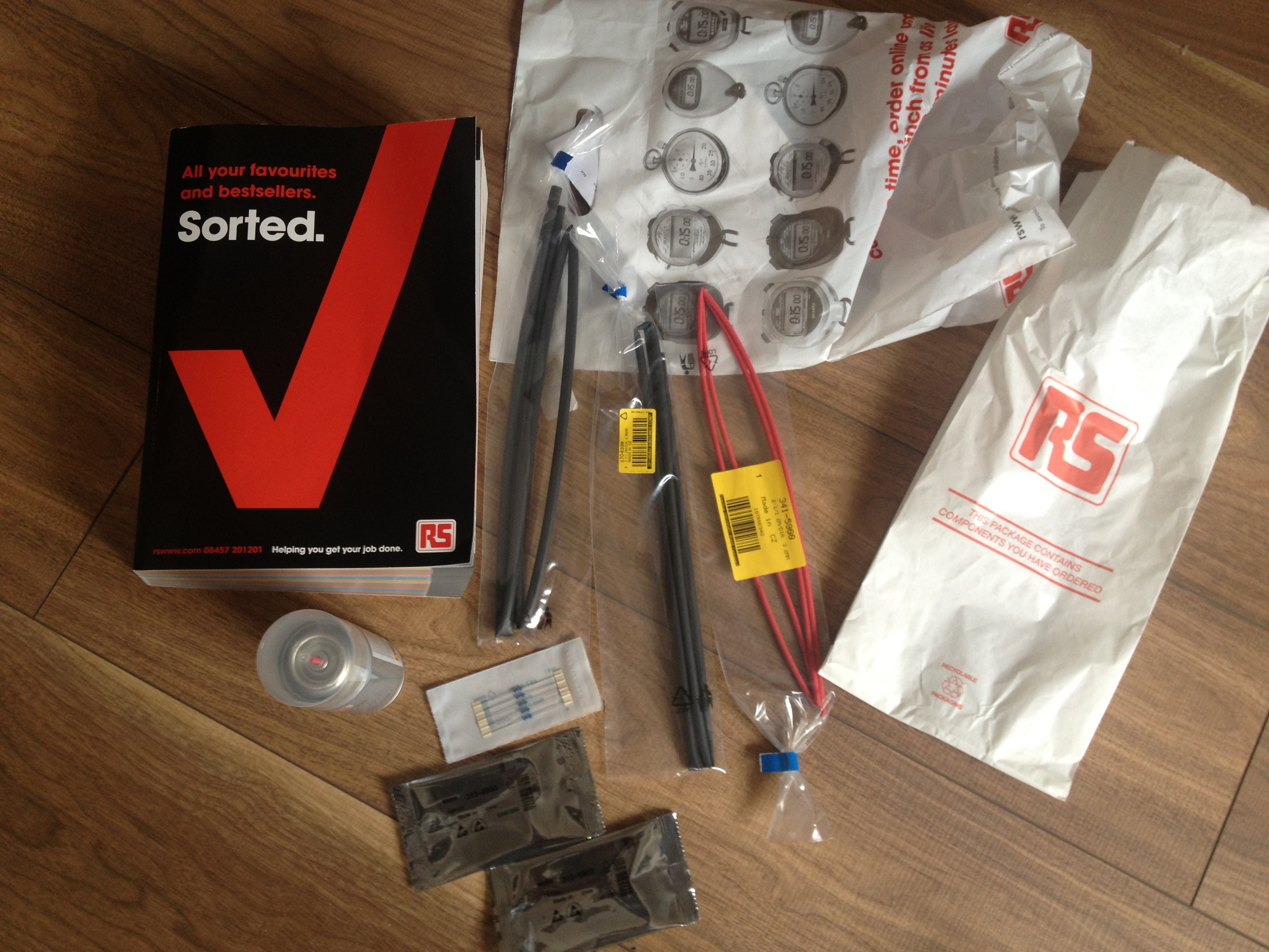
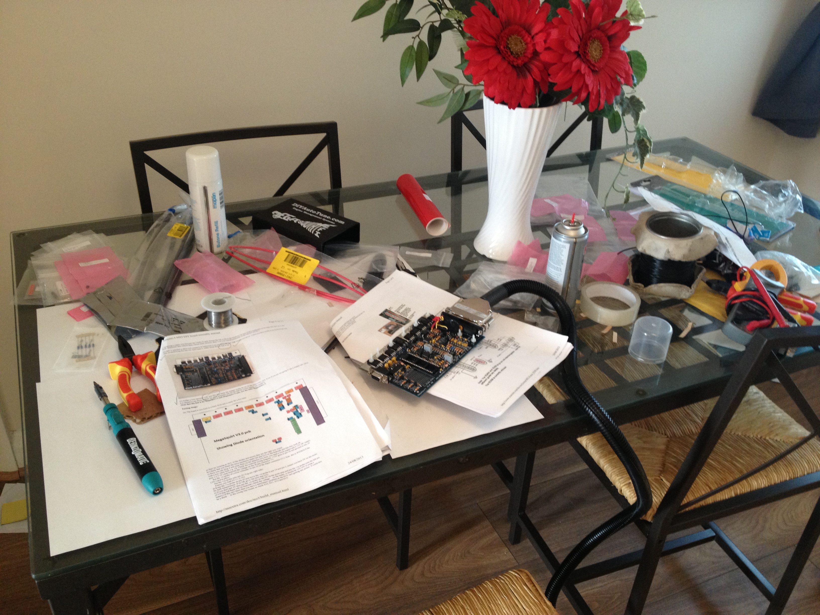
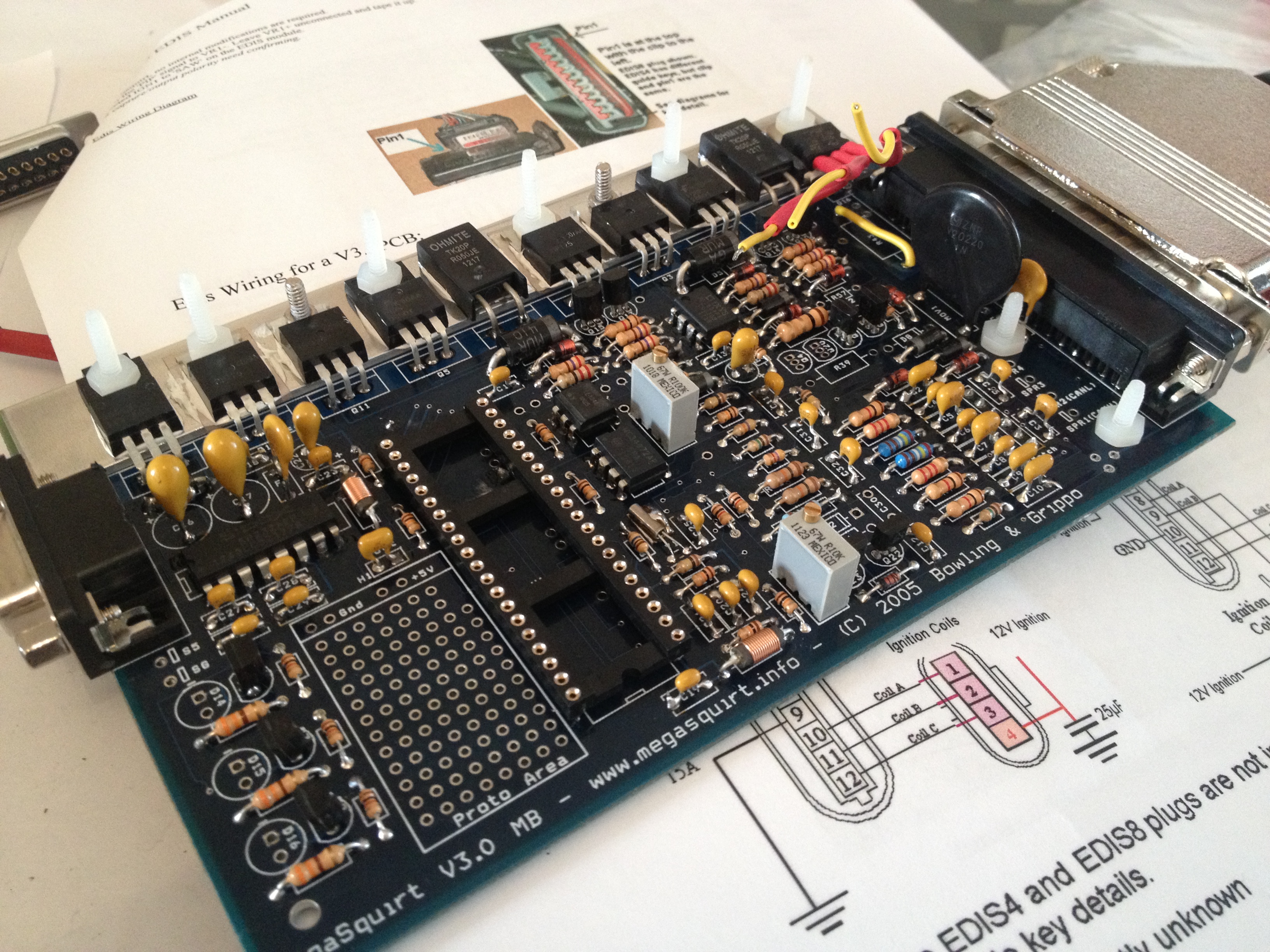
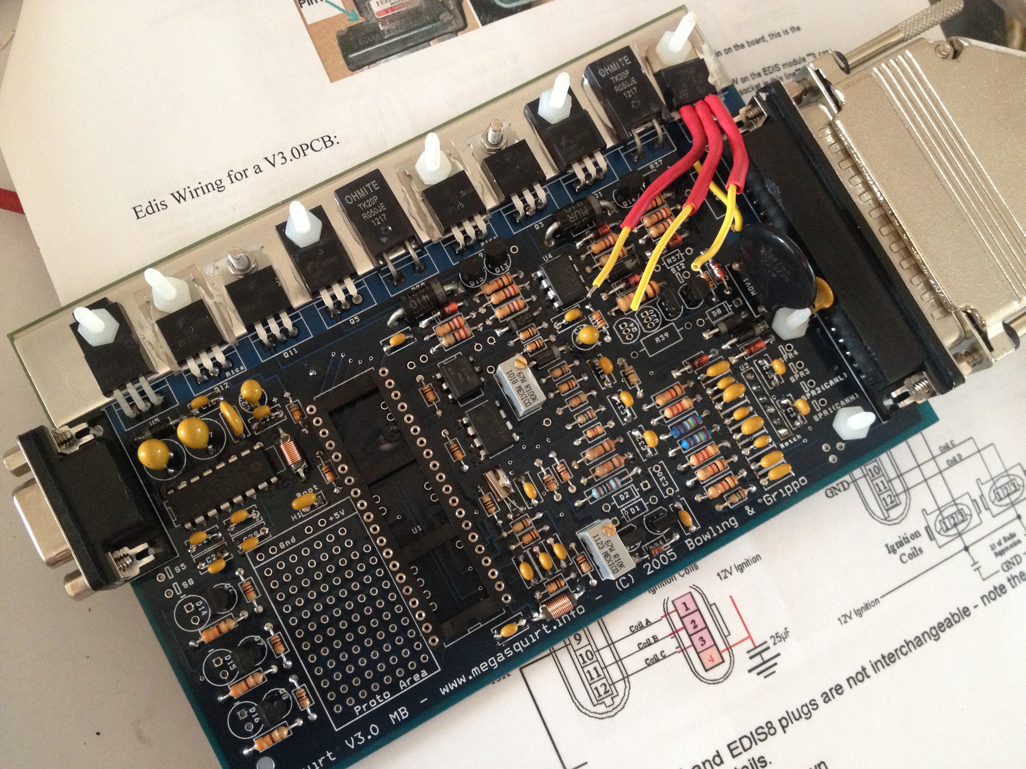
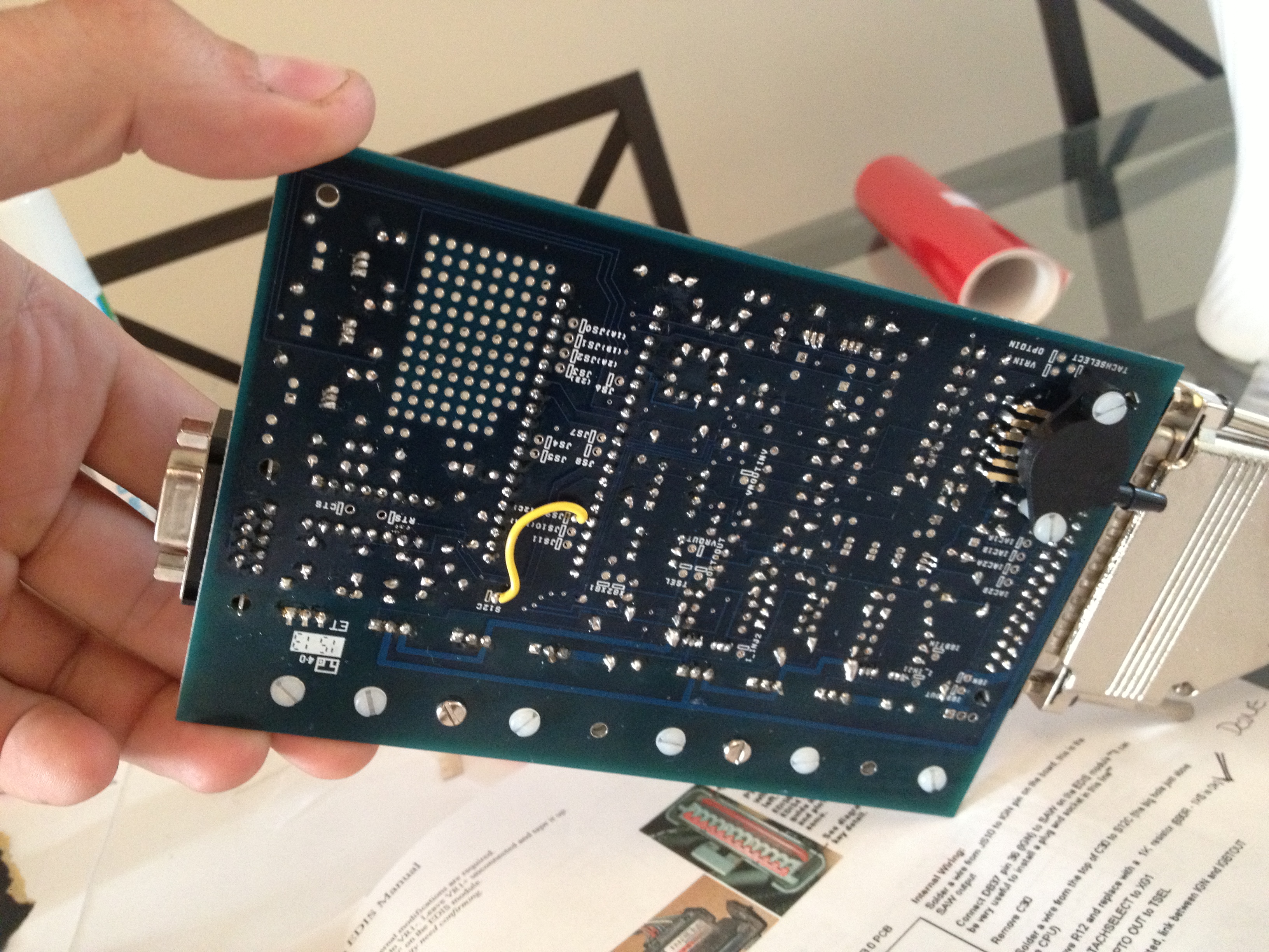
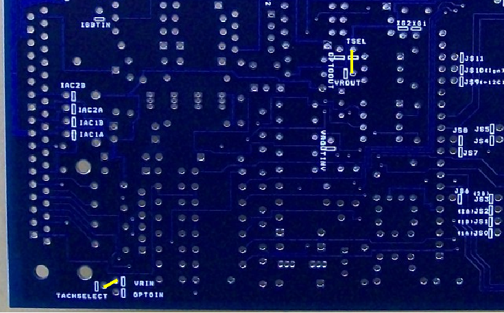
*Run the engine on Megasquirt
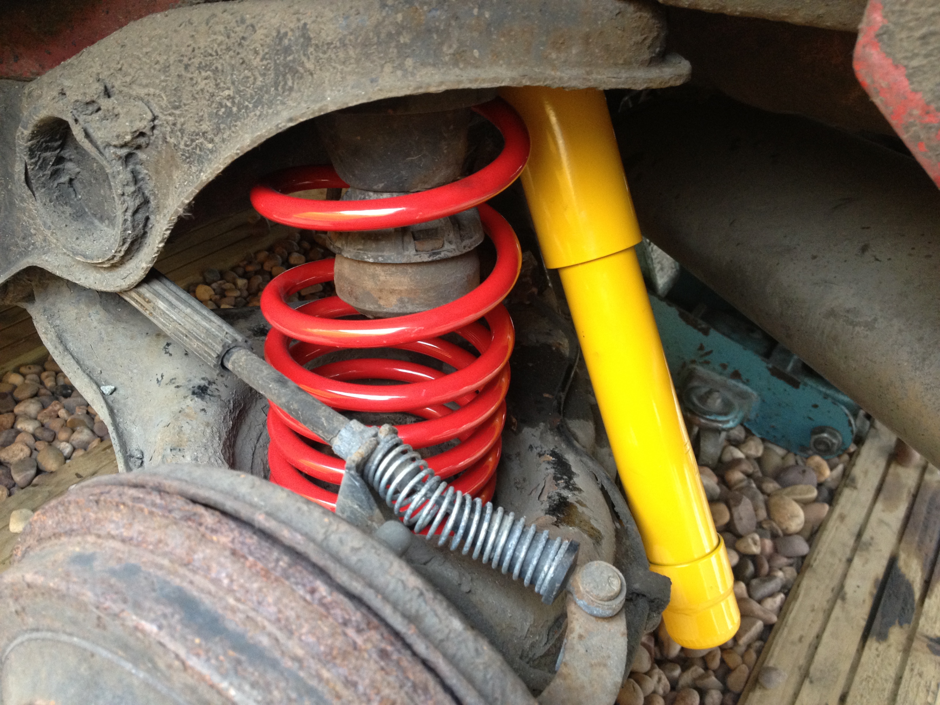
*Fit Coilovers to the new shell
*Install Full Poly Bush Kit
*UT Brake Upgrade
*Re design the engine mounts!!
I think the above is going to work out a fair bit, however I have openly admitted this car had a lot of problems in the past, so I am hoping to resolve these in the next shell to make it a more drivable car rather than something that's only good In a straight line.
The engine is due a rebuild (and apparently was in 2008), although after seeing how bad its been put together (wondering where the 18k was spent), I sadly don't believe a thing about the car and will be starting again from scratch!!!
The house move is due around November time, so I will be carrying out the bulk of the conversion then, although little bits will be done between now and then
As a few of you may know, I've had and done a good few seicento conversions in the past and was intending to do my mk2 c20xe (Vauxhall 2ltr) but this time around converting it to turbo (low boost).... Anyhow... As with most things in life, circumstances changed and buying a house took over, so this project sadly seen the bin!
The house took up a massive part of the year, as it needed fully renovating to bring it up to scratch, including rewiring, plastering new kitchen and so fourth... Due to me being self employed as an electrician/plumber, I ended up taking 3 months off work and doing the lot myself....
3 months later it went from this....
To this....
We got the keys originally in January this year, and now things have changed yet again as we have just accepted an offer on the house, and currently going through the sale process for it lol!!
However it now means the house we have put an offer on is much newer, requires hardly any work and the best bit.... I finally have a GARAGE
This is a first for me as im usually found outside in the rain and snow working on my cars....So now you know why I have been soo quiet, and why my last project was thrown to one side!!
Anyhow, onto the car!! Ive been secretly waiting for my old 1.4 seicento turbo to come back online for sale, always joking that if it did then I would buy it to strip into parts as it had a fortune 'apparently' spent on it (think upwards of 18k)....
Very recently, I had a text off todger, with an ebay item number
Thinking nothing of it i searched the number, and to my surprise the 1.4 seicento was on there for sale haha!! I rang todger and talked through whether or not it would be worthwhile to buy back, and we ended up making an offer to the guy for £650....As the car had a gearbox problem (solidly stuck in gear), it needed to be trailered upto me from Kent to Warwickshire for the grand sum of £135....
Anyhow, it arrived, and to be fair I had forgot how bad it looked.... what an eyesore..
As much as it looked bad when I owned it the last time, it has got progressively worse!... Its well known on the forum as a bit of a sl*g car due to the amount of owners it has had in its life....
It was apparently built by Wardy25 and his friend, with wardy paying for most of the work. From what I gather, there was a dispute of some sort between the two, and the car was never fully finished.. As you can see it wasn't mint, but it never used to look quite so bad...
No idea how its got into the state that its in now lol, but its time for me to change that!!
The original car is way too gone to save, and to be fair as I point out later, the engine conversion itself hasn't originally been carried out too great... Such things as the main engine mount being welded to the thin bay metalwork, and not to anything structural resulting in the mount passing through the bodywork... How was this repaired?... with the aid of exhaust rubbers mashed in-between the body and engine supporting it in place lol.
Ive started stripping the car down.... and NOT to my surprise I've found loads of reasons why this car has never actually ran properly lol..
The engine bay... Upon inspection at this point, things just look messy, but nothing screams out at you...
Then its time to uncover the electrics... (ignoring that the badly positioned stainless boost pipe work is arching out on the broken HT leads)..
All this lot was hidden in a plastic box in the engine bay....
There are exposed connections all over the place in the engine loom, for example the coil... Soldiered, practically all pins touching...
Relays
Dizzy slam panel mod... (as you can see the boost pipe runs across the HT leads, and with the friction it has worn through two leads creating obvious problems).
And then onto my favourite... The engine mounts....
With this beauty, it seems to have been welded to a single skin part of the car which has no under support as far as I can tell... The mount looks to have given way (well at least ripped the metal work apart)... and then fixed with perished exhaust rubbers... Im guessing by the look of the half width cambelt, the engine has dropped while running...
We then have this other 'custom' mount on the gearbox side.... (there is one to the rear, but I haven't got a pic yet... I will however as that's a beauty too)...
Other than the fact the wirings bad, the mounts are awful, its an eyesore, and the car is stuck in gear.. I think ive got a bargain... *rolls eyes*
The car is currently in this state, and im removing the salvageable parts off, to reclaim some money back and then put towards the rebuild & reshell...
I'm intending to...
*Fully strip the engine and rebuild
*Buy a replacement gearbox, or recondition the one I have
*Re-shell into a better donor car
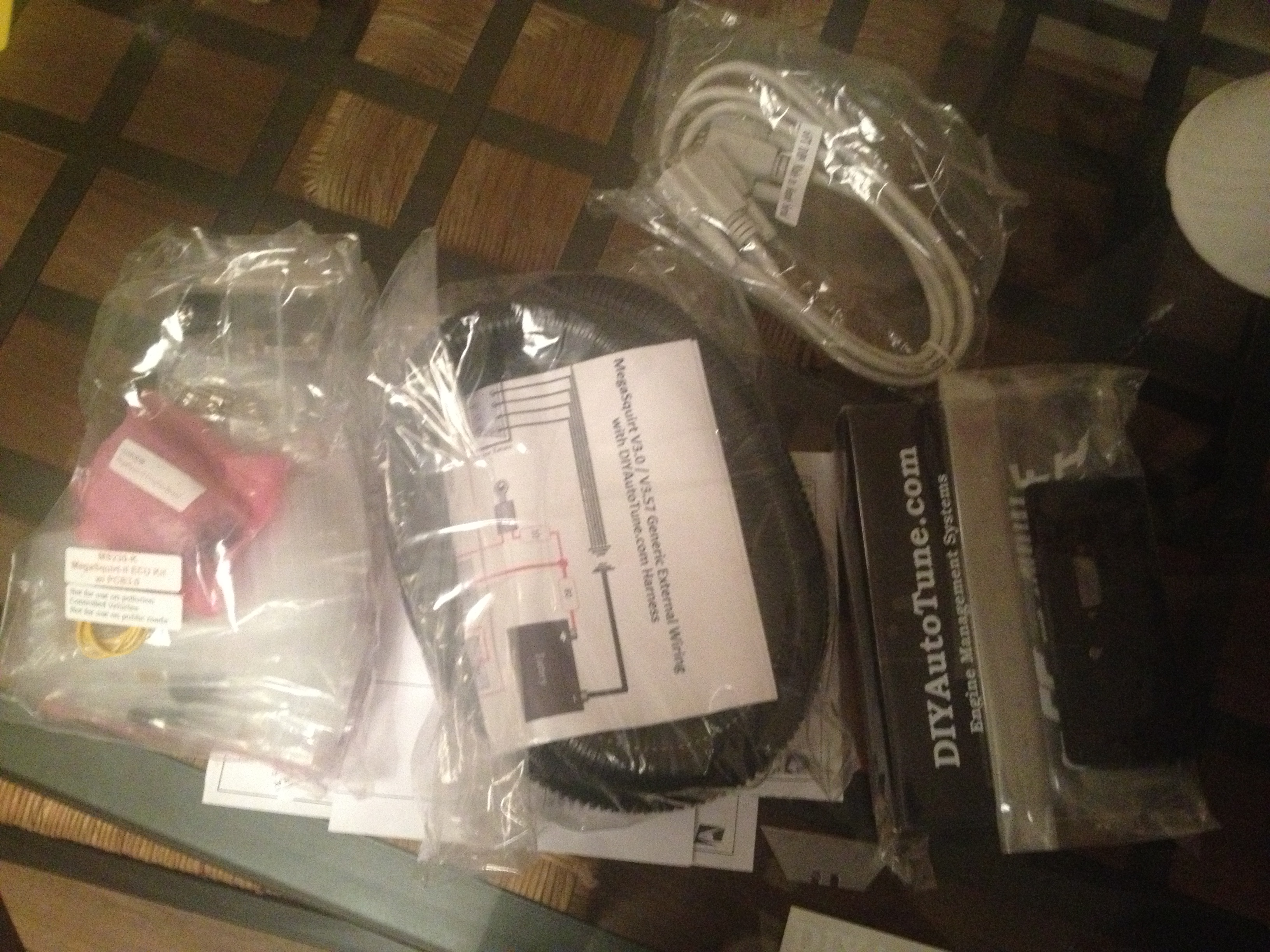
*Run the engine on Megasquirt
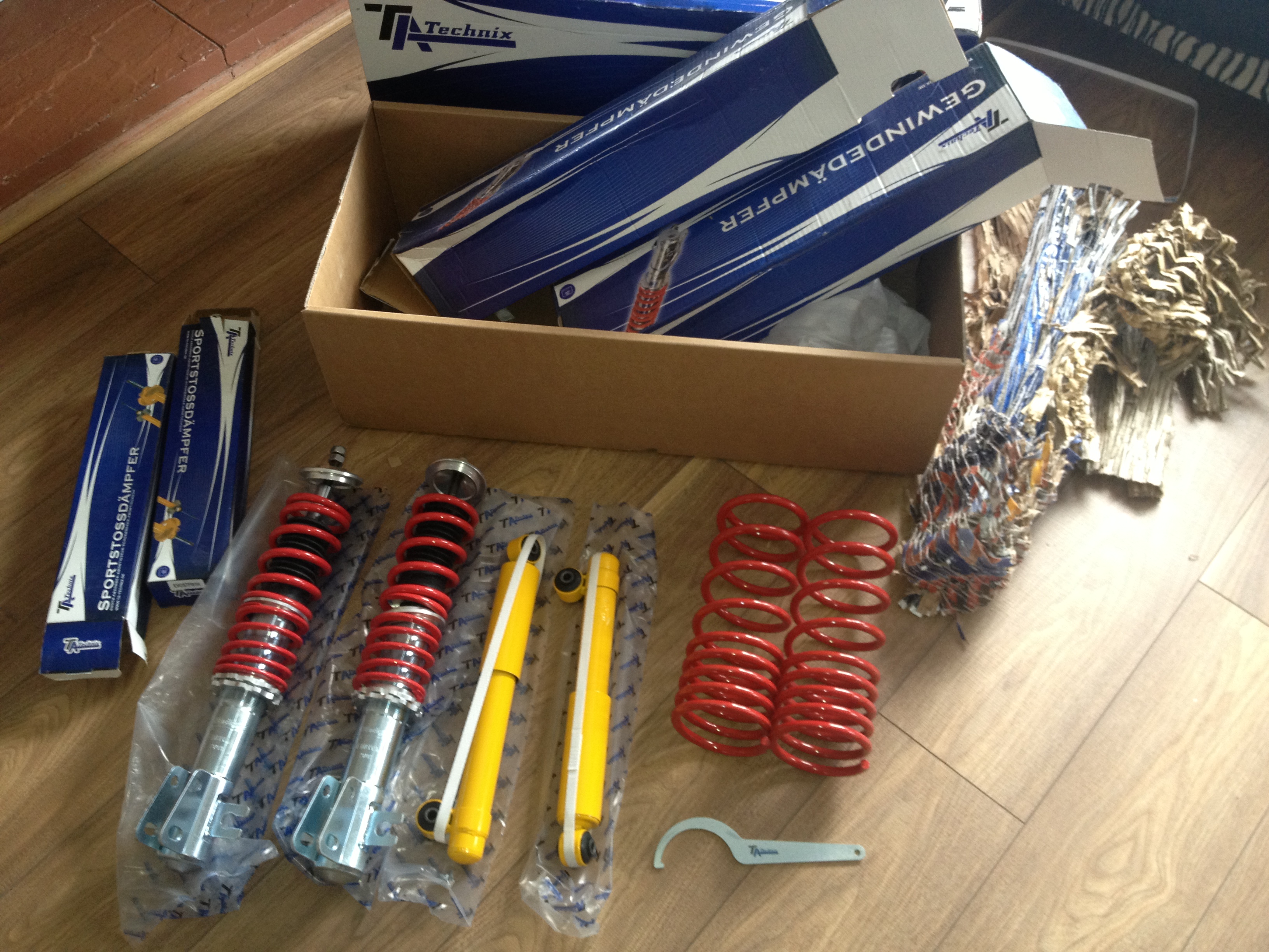
*Fit Coilovers to the new shell
*Install Full Poly Bush Kit
*UT Brake Upgrade
*Re design the engine mounts!!
I think the above is going to work out a fair bit, however I have openly admitted this car had a lot of problems in the past, so I am hoping to resolve these in the next shell to make it a more drivable car rather than something that's only good In a straight line.
The engine is due a rebuild (and apparently was in 2008), although after seeing how bad its been put together (wondering where the 18k was spent), I sadly don't believe a thing about the car and will be starting again from scratch!!!
The house move is due around November time, so I will be carrying out the bulk of the conversion then, although little bits will be done between now and then