Technical SPI Megasquirt Plug and Play Loom

Currently reading:
Technical SPI Megasquirt Plug and Play Loom

Joined
Feb 16, 2005
Messages
5,983
Points
988
I am looking to make a plug and play loom for the cinquecento and seicento SPI ECU, that will allow you too take a Megasquirt 2 ECU, and plug it directly in to the wiring loom, bypassing the standard ECU entirely.

This should end up being a working progress thread with all the information required, and also requesting information.

Purpose
I have a spare Megasquirt 1 lying about not being used. I would use this, but for plug and play compatibility we need to control the idle valve so this requires a Megasquirt 2 daughter board.

It will make a good basis for those who's ECU has failed. Those who fancy tuning easily for better economy or power. Those who have other mods planned down the line. Those who would like to easily learn the basics of ECU control.


Technical Doc's

As far as I can recall (without getting out and checking the car in the dark) the Cinquecento uses the following sensors. Tech sheets will be used to program the ECU.

View attachment PRT03.pdf -- The MAP sensor

View attachment ATS05.pdf -- The Air Temperature Sensor (inside Throttle body)

View attachment WTS05.pdf -- The Coolant Sensor

The Crank sensor, throttle position, idle valve, lambda and charcoal cannister won't require any technical sheets.

The only item that would be useful to identify will be the single injector. I'll strip my system in the coming weeks to try for a part number.

The wiring / loom

The megasquirt typically takes a vacuum line from the air intake, straight back to the megasquirt. I will be taking the output of the existing sensor, and running a wire back to the megasquirt instead.

I have used the seicento workshop manuals, and Arc's information in another thread to work out the basic outputs and inputs.

These are the pins we will need to connect too on the exisiting ECU loom connector:

Code:
1	white/green	coil pack 1					
2	green		idle controller
3	blue/yellow	idle controller
4	blue/red	fuel injection main relay (winding input)
5	
6	
7	
8	
9	
10	
11	blue/red	TDC sensor
12	brown/green	lambda -ve ref 
13	purple/white	Coolant signal
14	l blue/black	5v supply for MAP and TPS
15	
16	black		CTS, IAT, MAP, Lambda, DS, signal earth
17	green/black	main earth
18	pink/black	injector
19	l blue/red	coil pack 2
20	blue/white	idle controller
21	white		idle controller
22	orange/black	canister purge solenoid  
23	black/purple	fuel pump relay (winding input)
24	
25	
26	orange		injection relay (winding earth)
27	
28	yellow/black	TDC sensor
29	blue/yellow	lambda signal
30	pink		TPS signal
31	purple		Air sensor signal
32	yellow/red	MAP sensor (signal)
33	
34	grey/black	main ecu earth

I'll be listing where the wires will have to link to on the megasquirt side of the connector. Initially looking at it, there will be no further wires to link up for a fully working setup.

Now my first question?? Does anyone know where I can buy an ECU side connector for the standard ECU. This will save butchering an existing ECU. If I can't find a source, there's no much point me continuing. I can do it any old way and am happy to hack the entire car apart, but the point of this idea is to make it nice and easy for people.

I found an expensive US source. No good, but proves they are out there:

http://www.hpheaven.com.au/store/pa...sch-motronic-connector/?cat1=1&catid=0&page=5

People here struggled to find a connector and hacked it:

http://www.alfabb.com/bb/forums/eng...ne-management-using-stock-bosch-wiring-4.html

It's a Tyco / AMP / Bosch Motronics 35 pin ECU/PCB connector that's needed.

Any ideas? My search turned a blank.

If / Once i'ce finished this, I'll draw up a working tuning map as well, so you can just build a loom, plug and go :D Doing similar for MPI setups shouldn't be much harder to do either :)

Kristian
 
Last edited:
Good stuff, I'll ring them after the weekend.

Yeah, the Megasquirt box isn't suitable for the engine bay. It would still involve taking the 24 or so wires inside the car at some point, by some means, but thats not particularly hard.

I just liek the idea of someone being able to buy a MS off the shelf, make a cable, or get someone else to make it (probs and hour or less work), and then being able to just plug it in and drive :)


//Alternativly, the microSquirt is more than happy in the engine bay and can also do all of the above and comes pre-asembled, just at a higher cost.


http://www.diyautotune.com/catalog/microsquirt-engine-management-system-p-131.html
 
Last edited:
Can't help you with the ECU socket, I am afraid.

But :D it is an unbelievable coincidence, because I was thinking about the exact same thing last week (Friday to be exact :D), only for the VEMS ECU (which is practically a commercial version of MS from what I can tell). To cut the story short what I concluded after a brief research is that the relays (main and fuel pump) are causing problems. The source of the problem is that the stock ECU gets +12V fed through the relay coil (main relay), and on the fuel pump one it waits for +12V to appear at the coil (key-on). Then it switches both ECU pins (4 and 23 from what I can remember) to ground to switch the relays on. Don't remember exactly what followed, but I found it impossible to just plug-n-play the VEMS to the stock ECU connector without ripping out and modding other parts of the loom. Also, a bloke I know (he is actually registered here, but not active for a while) that is my electronic guru and hardware tester confirmed it is a problem. But we did not discuss the details. But surely you will figure it out on your own.

My guess it is also the reason for all MS users here for doing the loom from the scratch.
 
Very odd we had the same idea.

On the stock ECU we have two relays as shown. J10 powers coild, fuel pump, injectors etc.

J11 powers some of the ECU internals.

As you say both of these relays are controlled by the ECU which does pose a small problem.

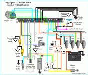
The megasquirt setup is supposed to be wired roughly like this:

v3ext_wiring.gif

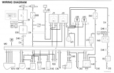
The stock schematics are this:

Capture.PNG


The soulution is simple though :)

Don't use J11!

Leave pins 4 and 35 floating, and run the ECU power from pin 26. A few amps should be more than enough to run the ECU and a few auxiliary sensors? this supply is fused on a 7.5 amp supply. Running a few amps through the ignition barrel will be no problem at all. This line is only high when the ignition is in crank and run positions I think. So turning off the ignition will turn off the ECU and de-energise J10.

Run pin 4 of the ECU to the fuel pump signal on the megasquirt. When the ECU then goes to a start and run condition if will ground this line and provide power to the coils, pump, injectors etc. If you have a stall event, it will cut the power

Should work? Not sure about how VEMS does it.

Kristian


//edit

The reason we have done it from scratch is it's more fun, and we are running different looms, MPI, different cars etc.
 
Last edited:
It is really too late and I am too tired to analyse all this. But:

Not using J11 is fine and in fact something I already figured out last week.

But then what about the fact that you will get +12V through the J10 coil (pin 23) once the ingnition is on? Will this not cause problem with MS? Also, pin 4 will have +12V at all times (hooked to the battery). So whereever it is hooked to MS, MS will have to be fine with it. If it is not, you cannot have neither of the relay coils (J10 or J11) connected to MS.

Mind you ;) we are talking about only making an adapter from the ECU connector to the MS. Without modding the rest of the loom at all.

Using pin 26 for powering the MS (or VEMS) is of course fine, for me it is not though, because I had to cut pin 26 connection (1.2 MPI ECU does not like it, drains the battery through it).
 
But then what about the fact that you will get +12V through the J10 coil (pin 23) once the ingnition is on? Will this not cause problem with MS?

No, shouldn't do. MS just grounds this pin, so 12v goes to earth. The coil in the relay acts as the load. This is what it's supposed to do

Also, pin 4 will have +12V at all times (hooked to the battery). So whereever it is hooked to MS, MS will have to be fine with it. If it is not, you cannot have neither of the relay coils (J10 or J11) connected to MS.

Leave pin 4 floating (no connection), J10 will work fine and there will be no side effects.

Shouldn't be any problems as far as I can see.

Strange about you're pin 26 lol
 
No, shouldn't do. MS just grounds this pin, so 12v goes to earth. The coil in the relay acts as the load. This is what it's supposed to do


Leave pin 4 floating (no connection), J10 will work fine and there will be no side effects.

Shouldn't be any problems as far as I can see.

I trust you, I know JS about electrics (believe it or not). Work out the ready diagram ;) it will make me understand all this better.

Strange about you're pin 26 lol

It is not strange, 1.2 MPI ECU does not use 26 pin the same way as 1.1/1.2 SPI. It does not use it for input, moreover, it apparently conveys +12V (from pin 4 presumably) to it when ignition is off. So what follows is that some receivers will keep getting +12V even with ignition off. But I never cared to see what is really going on, I just trusted some folks that said it should be done (pin 26 disconnected that is), it works perfectly this way, which means 1.2 MPI ECU indeed does not care about pin 26 (y)
 
I am running MS2 for more than two years, using a dummy box as a patch between MS2 and stock harness, which was not touched at all (except the 4 injectors instead of 1, as i am running 1242 8V). It's all written somewhere inside the Megasquirt topic.

As Woj said, i left 4 and 35 floating and got power from pin 26 through a 2A fuse. Never had a problem so far, MS gets power whenever the key is at ON or cranking. MS2 draws less than 2A, as coils, injector and other parts, draw power directly from relay J10. In fact i also have my wideband connected at pin 26 and draw another 2A without problem.

Pin 23 (fuel pump relay) should be connected to MS pin 37.

Original ECU gets 12V at pin 26 when key at on, probably asks immo if everything is ok and then grounds pin 35, main relay closes and the rest of the ECU wakes up through pin 4. Not needed in MS2, as all it asks is 1-1.5A and can take it directly through pin 26.

Kristian, pin 28 is TDC sensor + and pin 11 TDC sensor -, mark them right on your first post chart.
 
As Woj said, i left 4 and 35 floating and got power from pin 26 through a 2A fuse. Never had a problem so far, MS gets power whenever the key is at ON or cranking. MS2 draws less than 2A, as coils, injector and other parts, draw power directly from relay J10. In fact i also have my wideband connected at pin 26 and draw another 2A without problem.

I didn't say that ;) Kristian did (y)

Original ECU gets 12V at pin 26 when key at on, probably asks immo if everything is ok and then grounds pin 35, main relay closes and the rest of the ECU wakes up through pin 4.

I think the main realy (pin 35) is always switched on by the ECU, regardless of the immo state. The fuel pump relay is switched on only when immo is ok. Also, as I said before, only SPI ECU watches out for pin 26, 1.2 MPI does not, it watches out for power on pin 23 which it then grounds (provided immo ok) to ground to switch the fuel pump relay on.
 
Fuel pump relay is switched on for 2 seconds after key on and then stops. Then it starts again when crank sensor sends revs ton the ECU.
 
Good to know you've already done what I planned to do regarding power and wiring. I knew it would work fine as it's basic electronics. There wasn't any question really, but nice someone has done it before.

I had a look at the 1.1 MPi schematics, and they have a similar switched power, exactly the same function as the Spi pin 26, but on pin 17 instead (orange black)

Sadly I can't edit the original post, but if / when I've done all this, I'll make a proper guide and amend it there :)
 
I just finished soldering my second harness, this time i used the experience of those two years and made it MS3 ready. It now has wires for 4 coils, 4 injectors, camshaft wheel sensor, constant baro (will use stock MAP for this), boost valve, knock sensor, launch control, separate sensor ground, plus 12 more floating cables for future MS3 connections (Α/C clutch, fan, oil cooler fan, water injection, gear/speed sensor, etc).

This harness goes from MS (located under passenger dash), to a dummy ECU case inside engine compartment. All high current drivers (coil/injector/boost valve) will be mounted inside this box, to avoid interference inside MS box. Mini harnesses will leave the dummy box, towards coils, injectors and rest of the non-stock sensors (cam sensor, boost valve, knock sensor).

Dummy box was taken from a defective Punto ECU. Tons of them at auto electricians. In case someone needs help on this, just ask...
 
I seem to remember an old thread of yours with pictures? I can't seem to find it. Do you have a link or some pictures?

Bosch 227 100 211 will be good to mount in the dummy box if you are going sequential ignition.

My MS" has 4 injector outputs, 4 coil outputs, tach output, fan output, and cam input with modified crank input circuit. That's pretty much every available in/out used on the MS2/DB37.

The MS3 with the extra connector certainly does look good and I'd be interested to hear how it runs if you do the upgrade.

Kristian
 
Cheers :)

No I run 4 injector drivers on the board itself. I have no extra boards.

I used to use a driver board, and also a LM1815 board but moved it to the V3 PCB as it was neater.

I have mounted the two additional drivers where R37 and R38 used to be.

Kristian
 
Right....I have a connector thanks to Brooky :) I've chopped it off and have a DB37 all wired up with wires at the other end. I plan to just make a really simple adapter to start, soldering the other end to the ECU connector without heatshrinking etc, so that I can just link it up and see if it starts.

I'm pretty much set, apart from I need some new ignition drivers (collecting monday).

I am a bit confused on the Lamdba though. I've never looked at this as I have always run wideband.

It has 4 wires, Pins 3 and 4 go to 12V and earth and I presume are the heater? On the fiat schematics pins one and two go to the ECU. Is this simply a supply and earth? Can I wire either pin up to the MS and earth the other?

Looking forward to getting this up and running. Should be only a week or two :)

Roll on lean cruise decel cut decent fuel economy :D
 
Back
Top