Technical  Rusty bits - suspension

Currently reading:
Technical  Rusty bits - suspension

Update!
IMG_9129.jpeg

So if you look closely you see the remnants of that last bolt. And you see everything except the PB blaster that I used. Over. And over. And over. But success!

Thanks, gang
 
IMG_9130.jpeg

Sooooo….remember those lower ball joints? I had a friend suggest that I could cut one end of the riveted bits off and would then be able to remove them. Well… not really. See pic. Do I have to just suck it up and buy new lower A arms??
 
In my old days on American cars they could be ground off with an angle grinder, then punched out, and the replacement ball joints came with new bolts to replace them...or one could buy the entire control arm with the new ball joint riveted on...bet 124bc1 will have better advice!
 
The ball joint is riveted because it’s designed as part of the arm assembly.
Given the visible perforation and corrosion on the arm itself, replacing only the ball joint would not be safe or durable.
The correct repair is to replace the complete lower A-arm with ball joint pre-installed.
Attempting to drill out rivets and refit a joint into corroded metal risks movement or failure under load.

Thank you, yes - it seems like I might need to do that - and return the new ball joints I ordered….
You can do this if you want (to waste money!).

The Fiat dealer workshop approved method was to drill out the rivets and install a new balljoint and rubber boot using nuts and bolts which they supplied.
All the replacement suspension arms/wishbones I've seen come without a rivetted balljoint, the balljoint is either attached using nuts and bolts or the balljoint is supplied loose with nuts and bolts for the customer to install himself.
Some of the replacement bottom suspension arms don't have the factory type lower shock mounting instead they supply a separate bent metal strap to attach the lower shock mounting to the suspension arm - I don't like this type...

As long as the suspension arm is not heavily corroded or cracked (will need to be properly cleaned to verify) I'd be quite happy to fit a new balljoint and rubber boot using nuts and bolts - I did lots of them (back in the day) and none came loose or had any issues. I'd prefer to use Nyloc type nuts instead of plain nuts and spring washers, just be sure the nuts are the same strength as the bolts (afaik. metric 8.8 tensile strength). Alternatively, having installed the spring washers and nuts and tightened them, I'd fit additional plain nut to act as a lock nut (jam nut - old school engineering practice). Be sure to buy balljoints that are greaseable - if kept greased regularly, they'll last virtually forever (or until the rubber boot becomes eh. perforated....)

As regards removing the rivetted balljoints, all the 'shop manuals (I recall you have 2 types) say to centre pop the centre of each rivet head then drill to remove. I'd start with a 1/8" (3mm) drill and drill down deeper than the rivet head, then drill using a 5/16" (8mm) drill to the depth of the rivet head and no further, the rivet head just now pop off - don't drill into the suspension arm. When fitting the new balljoint, be careful to fit it the correct way around in the arm.

Also, fit new rubber bushes to the suspension arms while you have the opportunity, there are special tools available but not worth purchasing for a one-off job - I usually used a combination of offcuts of tubing with cut-outs to fit the shape of the arm plus suitably sized sockets and a bench vice to remove the old bushes and install the new ones. The top arm bushes are easy, the bottoms a little harder because of the bottom arm pivot. Access to a workshop press with suitable adaptors would make it easy.
 
Last edited:
View attachment 481649
Sooooo….remember those lower ball joints? I had a friend suggest that I could cut one end of the riveted bits off and would then be able to remove them. Well… not really. See pic. Do I have to just suck it up and buy new lower A arms??
That's one way to remove the balljoints. You haven't damaged the arm, just gouged the balljoint body a little, no real harm done.
Iirc, drilling the rivet heads off from the other side is easier (afaik, the other side is the original head of the rivet and is more circular so easier to find the exact centre and may also be a little thinner).
 
When preparing the lower suspension arms check the shock mounting carefully for cracks and clean up the threads for the anti-roll (sway) bar mounting (I saw slightly damaged threads in one of your pics). If the threads are not recoverable, a new bolt can be welded in to replace a damaged stud quite easily while the arm is off the the car.
 
You can do this if you want (to waste money!).

The Fiat dealer workshop approved method was to drill out the rivets and install a new balljoint and rubber boot using nuts and bolts which they supplied.
All the replacement suspension arms/wishbones I've seen come without a rivetted balljoint, the balljoint is either attached using nuts and bolts or the balljoint is supplied loose with nuts and bolts for the customer to install himself.
Some of the replacement bottom suspension arms don't have the factory type lower shock mounting instead they supply a separate bent metal strap to attach the lower shock mounting to the suspension arm - I don't like this type...

As long as the suspension arm is not heavily corroded or cracked (will need to be properly cleaned to verify) I'd be quite happy to fit a new balljoint and rubber boot using nuts and bolts - I've did lots of them (back in the day) and none came loose or had any issues. I'd prefer to use Nyloc type nuts instead of plain nuts and spring washers, just be sure the nuts are the same strength as the bolts (afaik. metric 8.8 tensile strength). Alternatively, having installed the spring washers and nuts and tightened them, I'd fit additional plain nut to act as a lock nut (jam nut - old school engineering practice). Be sure to buy balljoints that are greaseable - if kept greased regularly, they'll last virtually forever (or until the rubber boot becomes eh. perforated....

As regards removing the rivetted balljoints, all the 'shop manuals (I recall you have 2 types) say to centre pop the centre of each rivet head then drill to remove. I'd start with a 1/8" (3mm) drill and drill down deeper than the rivet head, then drill using a 5/16" (8mm) drill to the depth of the rivet head and no further, the rivet head just now pop off - don't drill into the suspension arm. When fitting the new balljoint, be careful to fit it the correct way around in the arm.

Also, fit new rubber bushes to the suspension arms while you have the opportunity, there are special tools available but not worth purchasing for a one-off job - I usually used a combination of offcuts of tubing with cut-outs to fit the shape of the arm plus suitably sized sockets and a bench vice to remove the old bushes and install the new ones. The top arm bushes are easy, the bottoms a little harder because of the bottom arm pivot. Access to a workshop press with suitable adaptors would make it easy.
Thanks, @124BC1 - Yeah, I think I'm going to do the drilling approach (thanks for those details), and my initial cleaning did not reveal any cracks anywhere. The replacement ball joints, which I already have, do come with the nylock nuts I believe. Removing the old bushings is going to be a task - I've made one pass at it with my bench vise and a large C-clamp and a couple of sockets, but I think the penetrating oil needs more time, and maybe I can grow a 3rd arm to hold all those bits in place at the same time (lol). I'll try drilling on the rivets and report back...
Oh and the new lower arms are $150 apiece before taxes and shipping...
 
The systems are coming together; fuel lines and tank are mostly in, new brake master and I’ve just refurbished the calipers, now the outer suspension, then I should be able to drop it and insert the noisy bits. Assuming I get the dash and electrical hooked up….
Just had a thought for your consideration...

Seeing as you have nearly all the front suspension removed...
If you remove the front crossmember (and the centre track rod - I always forget about this item), you could position the engine fully assembled with most ancillaries fitted plus transmission (including the gear shift lever) under the car (you may already have it high enough) and use an engine crane to lift the whole engine/transmission assembly up into the car then just refit the engine crossmember and transmission crossmember and job done - no messing with getting the engine up high enough and at the correct angle for insertion - so much easier and little risk of damaging anything including paintwork.
 
Just had a thought for your consideration...

Seeing as you have nearly all the front suspension removed...
If you remove the front crossmember (and the centre track rod - I always forget about this item), you could position the engine fully assembled with most ancillaries fitted plus transmission (including the gear shift lever) under the car (you may already have it high enough) and use an engine crane to lift the whole engine/transmission assembly up into the car then just refit the engine crossmember and transmission crossmember and job done - no messing with getting the engine up high enough and at the correct angle for insertion - so much easier and little risk of damaging anything including paintwork.
Oooooooohhhhhhh! Let me think about this - my working spaces (as I may have mentioned) are very tight and your suggestion is really interesting as I do have the engine / trans reassembled and ready to place. That is inside the shed, still attached to the large crane I have, and resting on a box I built. I could lift it a bit, and wheel it (engine / trans) towards the car - which is currently outside but under an awning roof - and then figure some way to slide it under, after removing the crossmember and steering stuff... then reattach the crane....

I'm going to park that idea. Thank you for that, as I was feeling trepidacious (yes, I'm making that a word) about lifting all my hours and hours of work that high in the air, and then managing a precipitous angle....
 
Oh and the new lower arms are $150 apiece before taxes and shipping...
So that would be $300 plus taxes/shipping.
And then of course, you may as well get new upper arms as well...
Plus springs.
plus shocks.
The list can so easily get very long and very expensive, if you don't exercise restraint.
BTDT, I try to rein in others, but do they listen?....
 
Oooooooohhhhhhh! Let me think about this - my working spaces (as I may have mentioned) are very tight and your suggestion is really interesting as I do have the engine / trans reassembled and ready to place. That is inside the shed, still attached to the large crane I have, and resting on a box I built. I could lift it a bit, and wheel it (engine / trans) towards the car - which is currently outside but under an awning roof - and then figure some way to slide it under, after removing the crossmember and steering stuff... then reattach the crane....

I'm going to park that idea. Thank you for that, as I was feeling trepidacious (yes, I'm making that a word) about lifting all my hours and hours of work that high in the air, and then managing a precipitous angle....
It was just an idea I had. No harm in doing it the traditional way in your situation given your workspace arrangements - the idea might help someone else. A load-leveller attachment for your engine crane (I can't remember if you had one originally) and someone to assist would help greatly. As regards feelings of trepidation (and this word does exist! I checked ;)), don't forget - 'a problem shared is a problem halved', plus, if something does go wrong, you can always blame the other person :devilish:

On many small modern front wheel drive cars the engine/trans, is dropped down and out, not lifted up and out - those who have a car hoist/ramp usually position a mobile work bench underneath to receive the engine/trans, makes it really easy (as seen on various car repair/resto tv programs).

As regards your rebuilt engine and transmission, I meant to suggest earlier that if the engine is left sitting for an extended period of time, it might be worth pouring some engine oil down the spark plug holes and rotate the crank. if you haven't already done so. Also ref. your rebuilt trans.? did you check that all gears can be selected without difficulty after final assembly - nothing worse that refitting a rebuilt trans. into a car and then finding there's a problem and it has to come out again.
 
It was just an idea I had. No harm in doing it the traditional way in your situation given your workspace arrangements - the idea might help someone else. A load-leveller attachment for your engine crane (I can't remember if you had one originally) and someone to assist would help greatly. As regards feelings of trepidation (and this word does exist! I checked ;)), don't forget - 'a problem shared is a problem halved', plus, if something does go wrong, you can always blame the other person :devilish:

On many small modern front wheel drive cars the engine/trans, is dropped down and out, not lifted up and out - those who have a car hoist/ramp usually position a mobile work bench underneath to receive the engine/trans, makes it really easy (as seen on various car repair/resto tv programs).

As regards your rebuilt engine and transmission, I meant to suggest earlier that if the engine is left sitting for an extended period of time, it might be worth pouring some engine oil down the spark plug holes and rotate the crank. if you haven't already done so. Also ref. your rebuilt trans.? did you check that all gears can be selected without difficulty after final assembly - nothing worse that refitting a rebuilt trans. into a car and then finding there's a problem and it has to come out again.
Oh yes, I have a load leveler on the crane and a combination of lifting straps and chains. I’ll think more about the options for reuniting.
Regarding the sitting engine, yes it’s time I put some oil on the pistons - it has been a couple of months. AND I did push the shifter through the positions to check the trans but also am wondering if there is a really good way to verify function - maybe it’s about turning the motor and checking the output shaft rotation speed / direction ?
 
Removing the old bushings is going to be a task - I've made one pass at it with my bench vise and a large C-clamp and a couple of sockets, but I think the penetrating oil needs more time, and maybe I can grow a 3rd arm to hold all those bits in place at the same time (lol).
You might practice on changing the top arm bushes to develop your technique. The lower arm bushes will require a bit of ingenuity. Iirc, once one of the lower bushes has been removed, the centre pivot bar can be removed and then you have easy access to press out the remaining bush.

A couple of possible ways to remove the old bushes:-
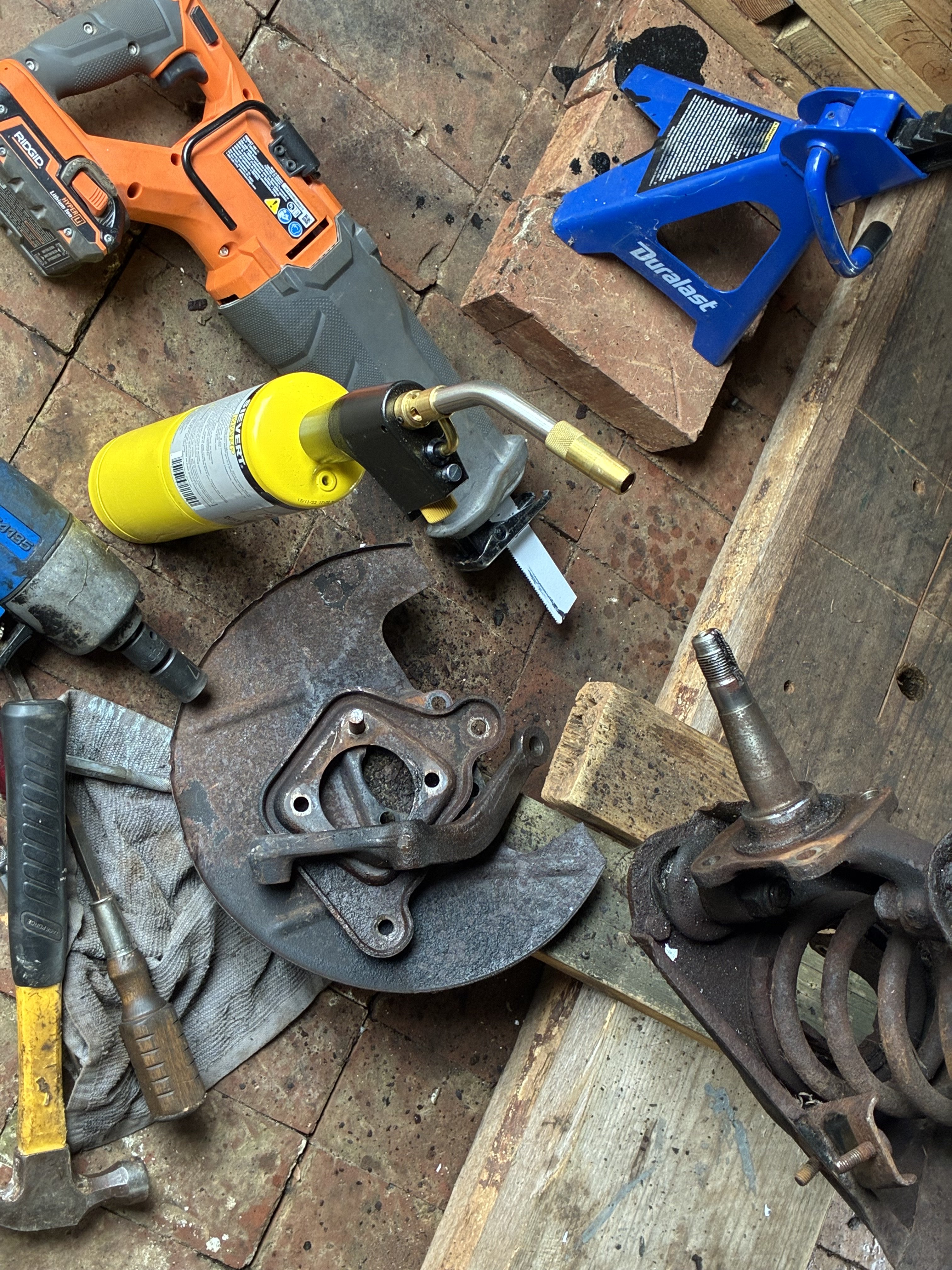
If you examine the arms where the bush is held, you'll see that a hole is punched through the arm and the metal folded over to form a little ring or tube - this is what holds the bush in place. This ring area is where heat is best applied (using your shiny new gas torch(y)), I find that heating and spraying penetrating fluid on tends to draw the fluid into where it's needed (don't breathe in the fumes when doing this).

Another way is to destroy the bush.... Cut through the rubber, (more difficult that it sounds, on heavy trucks we used to burn out the rubber but the fumes are deadly), a reciprocating saw (sawsall?) with a small blade might work, woodworkers might use a coping saw or a junior hacksaw i.e. disconnect one end of the blade, insert through a hole made in the rubber, reconnect the blade and saw away. With the rubber and inner metal bush removed, it would be possible to do the same to get a hacksaw blade into the now large hole and carefully saw through the wall of the outer metal of the old bush, causing it to collapse and be easily removed.
 
I did push the shifter through the positions to check the trans but also am wondering if there is a really good way to verify function - maybe it’s about turning the motor and checking the output shaft rotation speed / direction ?
I don't think you had enough of the transmission apart (iirc, you didn't strip the shafts/gears out?) to cause any problems.
My main concern was that those pesky little balls/beads went back in the correct order.
The 3 balls and springs under the little plate on the side of the trans. are what hold each gear engaged i.e. stop it dropping out.

The little ball/beads? that fell out when you turned the trans. over with the bottom pan removed are interlock devices -these ensure that only one gear can be engaged at any one time (if 2 gears were engaged at the same time it would cause the trans. to lock because the countershaft would be trying to drive the output shaft at 2 different speeds at the same time).
As long as you can engage and then disengage each gear using the shift lever, everything should be fine. You might find that you have to wiggle the output flange on the trans. back and forth to engage some of the gears, this is only because some of the teeth in the synchromesh units are not aligned when the gears are at rest. This is normal and nothing to be trepiditious about :giggle:.

I don't think there's any need to turn the engine over to test the gears.
 
I don't think you had enough of the transmission apart (iirc, you didn't strip the shafts/gears out?) to cause any problems.
My main concern was that those pesky little balls/beads went back in the correct order.
The 3 balls and springs under the little plate on the side of the trans. are what hold each gear engaged i.e. stop it dropping out.

The little ball/beads? that fell out when you turned the trans. over with the bottom pan removed are interlock devices -these ensure that only one gear can be engaged at any one time (if 2 gears were engaged at the same time it would cause the trans. to lock because the countershaft would be trying to drive the output shaft at 2 different speeds at the same time).
As long as you can engage and then disengage each gear using the shift lever, everything should be fine. You might find that you have to wiggle the output flange on the trans. back and forth to engage some of the gears, this is only because some of the teeth in the synchromesh units are not aligned when the gears are at rest. This is normal and nothing to be trepiditious about :giggle:.

I don't think there's any need to turn the engine over to test the gears.
Whew - well that makes me feel better about the transmission. I did carefully replace all the balls / beads / springs / dowel bits both on the side and through the vertical gaps in the actuating rods (I'm making up more terminology here). It *seems* to be functional, so I'm just going to say it's fine and go back to crafting ways to destroy old bushings. :Nothing to be trepiditious about. I'm going to go ahead and take the right assembly off (spring / control arms) so I can line them all up and perfect a methodology.
 
New, fresh he** :). Why would someone have put a spot weld on the nut for the lower A arm ?? Sigh. I’ve tried grinding a bit; the impact just spins the bolt around. Am I right that I’m going to need to cut it off and get a replacement bolt?
Meanwhile: I’m cleaning parts.
 
Perhaps message 124bc1 , I bet he will have a solution...is it possible to clamp a wrench or socket on the end that's spinning with a c clamp or something to prevent it from spinning? Get as much of the tack weld ground off as you can, then lay on the impact big time...perhaps it will bust loose? Hopefully with a 1/2" impact...I would try that before cutting, who knows you might even be able to save the bolt when you get it out by running a die over it depending on how much someone boogered it up by welding it..
 
Perhaps message 124bc1 , I bet he will have a solution...is it possible to clamp a wrench or socket on the end that's spinning with a c clamp or something to prevent it from spinning? Get as much of the tack weld ground off as you can, then lay on the impact big time...perhaps it will bust loose? Hopefully with a 1/2" impact...I would try that before cutting, who knows you might even be able to save the bolt when you get it out by running a die over it depending on how much someone boogered it up by welding it..
Yeah thanks @Slotman - I do think it’s sufficiently boogered to merit cutting off and sourcing a new bolt; but I am employing my time-tested methodology of “walking away” to let the problem lie for a bit, and to collect some wisdom from you and others here !
 
New, fresh he** :). Why would someone have put a spot weld on the nut for the lower A arm?? Sigh. I’ve tried grinding a bit; the impact just spins the bolt around. Am I right that I’m going to need to cut it off and get a replacement bolt?
Meanwhile: I’m cleaning parts.
I'm not sure which nut or bolt you're referring to, a pic or a better description might help.

Maybe you mean one of the 2 nuts that attach the lower A arm pivot to the crossmember?
In which case the bolt that is just spinning around might be one of the 2 studs that clamp the lower A arm pivot to the crossmember?
These studs are similar to bolts but don't have a hex head, instead they have a flat round head with a flat on one side to locate them (and stop them from turning) in the crossmember - they usually have a spot weld on the head to prevent them from turning. I don't know if they are available as a spare part but a regular bolt of the correct size/thread could likely be slightly modified by grinding its head to fit as per the original.

When faced with situations where someone has spot welded 2 things together that were designed to be easily separated, in your case a nut and bolt, sometimes it's easier to split/cut off the nut instead of the bolt - there are 'nut splitter' tools available or a cut-off disc can be used but gaining sufficient access is often a problem, sometimes a hacksaw can be used or 2 holes drilled through the length of the nut (i.e. inline with the bolt) to weaken it and then split it using a chisel.
Then with things disassembled, you hopefully have access to tidy up the thread on the bolt. Sometimes a proper 'Thread File' is a better tool for thread clean-up than a thread die-nut, you could also use a small triangular (3 corner) or knife edge file.
There's lots of videos etc. on restoring damaged threads including the use of thread files and similar tools.

Some people are very adept (sometimes too quick!) to use a gas cutting torch or perhaps, nowadays, a plasma cutter but I've become very gentle in my old age... Many people now have angle grinders but these can be quite brutal tools and with sparks flying you can't monitor how things are progressing - I prefer an old school hacksaw or blade in a pad handle (hole saw?) plus a hand file - it's easy to avoid removing too much material manually. Modern workshop might use an induction heating tool but this won't help with a spot-welded thread issue.

P.S. Cleaning parts is always a good option (and use of your available time) when things seem to be going badly - sometimes while doing something different, a possible solution to deal with the setback just pops into your head (a bit like when you 'sleep on a problem').
 
Last edited:
Back
Top