Hi!
I've never attempted something like this before, so please go easy on me and if there are any errors or omissions, please let me know")
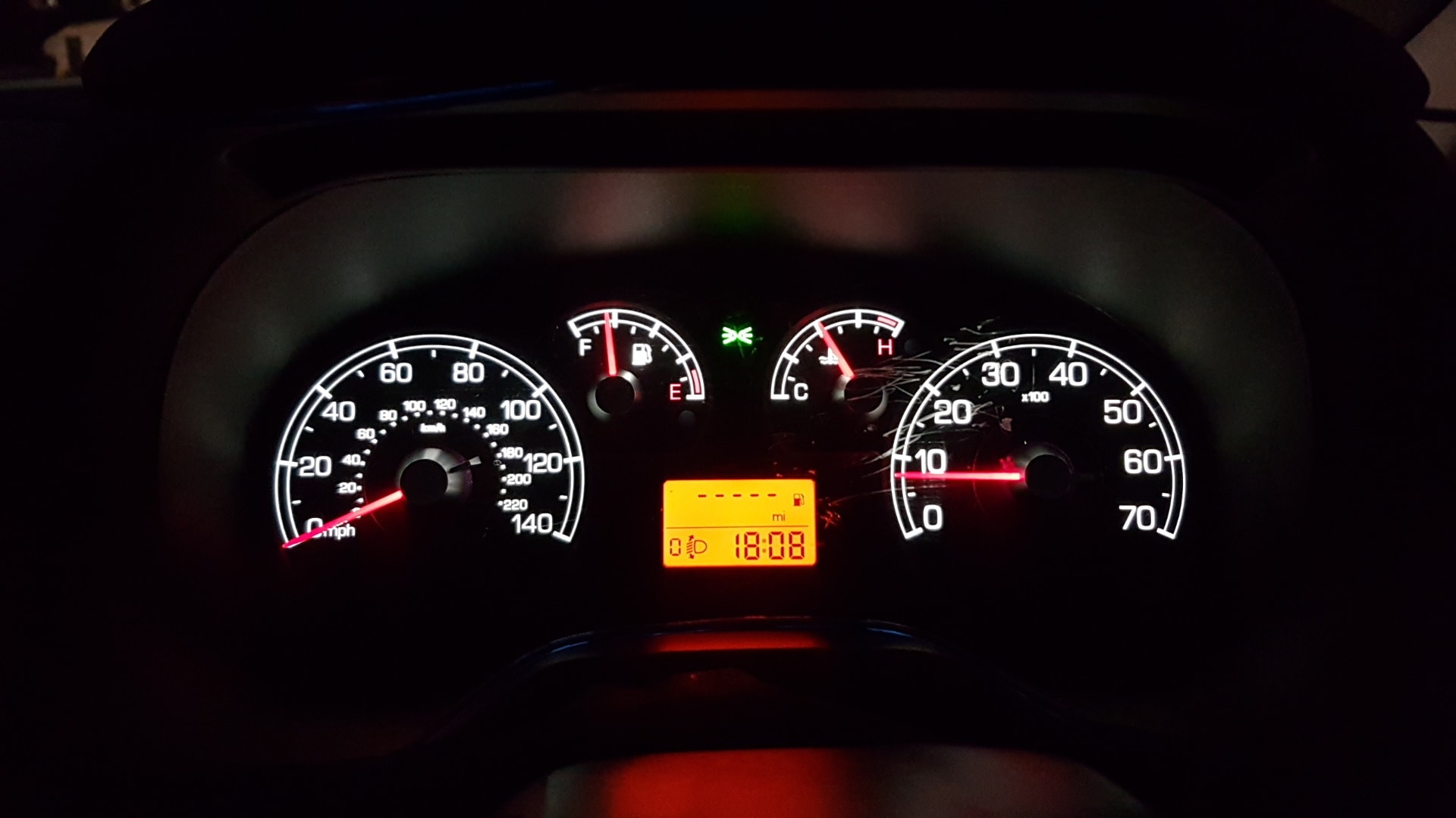
I'd wanted to change the horrible Fiat orange dash colour ever since I got my Mk3/ MK2b, but never did. Reality was that I was worried that I'd stuff it up.
Everywhere I looked, I could only find articles on the Punto Mk2, and even those were not really complete or a 'step by step' type of guide. For example, my biggest problem was how to refit and align the needles correctly.
The idea behind this guide is to provide an easy step by step guide with photos on how to go about changing the colour of your instrument cluster. I will also include a list of materials and equipment that you will need. Hopefully this will answer 100% of your questions.
The most important thing you need to remember – take your time, take your time and just in case I wasn’t clear before, take your time.
DON’T rush the job.
Materials Required:
3528 PLCC-2 LED's of whatever colour you prefer
- 6x for cluster illumination
- 4x for needles
- 3x for LCD
- 5 or 6 for switch rail (if you decide to do this as well)
Translucent filter, 10cm x 7cm so it can be cut to size)
20-25W soldering iron, preferably with 2mm tip or a variable temperature soldering station ( I used an Antex 660TC with a 25w iron)
1mm thick rosin core solder (you'll need less than 50cm)
Flux paste (eg: Amtech RMA -223 or similar)
Decent pair of tweezers, hobby cutting knife, long nose pliers, small philips screwdriver, small flat blade screwdriver, Hex bit set (for removing dash).
Where can I buy?
I bought my LED's and the translucent filter from a company called Crazyled's (www.crazyleds.co.uk). Before buying I got in contact with one of their pre-sales support guys called Mike Horn. Very very helpful person.
The blue LED's cost UK 0.21p and the red LED's UK0.24p each. The translucent filer cost UK Pounds 1.40.
Rosin solder, soldering iron, flux paste, tweezers and all the other tools can be bought from any decent electronics or hardware store like Farrells or possibly even Maplin (B&Q is NOT recommended).
Where do I start?
First step is to disconnect the negative battery lead. This is to ensure that nothing goes wrong with the electricals.
Whilst not critical, it is preferable that you do this with a full tank of fuel, as it makes it easier when refitting the fuel needle.
Next, is to remove the fascia surrounding the instrument cluster (the dash). There are 4x T15 hex screws holding the fascia in place. Two are located under the top part (run your finger between the clear glass and the black fascia to locate them) and one screw on either side of the steering wheel.
Once you have removed the fascia, you will need to remove the 3x T20 hex screws holding the cluster in place. One screw is located dead centre at the top and one on either side of the dash, bottom corner.
** It is not necessary to do so but if you wish, and if you feel comfortable doing so, you can remove the steering wheel to get better access to the dash **
Carefully lift out the dash for 10-15cm and feel behind the top right corner. You will find the dash connector. It has a locking mechanism which keeps it in place. Press the top part of the connector and depress the lock, the lever will free itself and allow you to unclip the connector from the dash.
Remove the dash, turn it over and remove the 4 small Philips screws. This allows you to open and separate the cluster. Remove the clear glass from the front of the dash. Clip the connector block back, reconnect the battery terminal and switch the ignition on. Do NOT start the car.
This next part is very important, so take lots of care. With the ignition on and without touching the needles, take a pencil or marker of some sort and mark the position of each needle.
Switch the ignition off, remove the key and repeat the process. You should have 2 marks for the Speedo and the Rev counter and 1 each for Petrol and Temperature.
Disconnect the battery as before. Unclip the dash connector and remove the dash to your workbench.
Whew!! So far so good… what next ?
With the dash securely on your workbench, carefully and slowly rotate the speedo and rev counter needles clockwise until you feel a resistance and they stop moving. DO NOT FORCE THE NEEDLES FORWARD. Carefully mark this position as well. You should have 3 marks by now, for the speedometer and rev counter, and one each for the fuel and water temperature.
Using the small flat blade screwdriver, carefully prise off the black cap covering each needle. With the long nose pliers, simply pull the needles up and off (they slide on a spindle).
Turn the dash over and unclip the pc board (there are 5-6 clips) from the dash faceplate (the black part with the white numbers etc). This is what you will see:

If you are also going to replace the LED’s for the LCD screen, turn over the pc board and unclip the metal lugs holding the LCD housing. Remove the housing from the PC board.


If you are going to use any other colour except red or orange for the LCD display, you will need to remove the translucent filter. With extreme care turn over the LCD, slide it out of the housing and store it somewhere safe.

Remove the yellow translucent filter and replace it with one cut to size from the white translucent sheet you bought originally. I used blue LED’s and would have preferred to get a translucent sheet with a blue tinge to give it a uniform colour, but was not able to find one. Probably does exist… somewhere ..


Soldering and desoldering
Ok, this is the probably the most important part. By now you should know exactly which LED’s you are going to change. If you don’t…… you are probably reading the wrong guide
Before doing anything take a blank sheet of paper and mark the position and notching of each LED you are going to replace. Depending on the brand some LED’s are numbered on each corner, but all have a notch in the top right corner (corner #3). Trust me, this will help you no end when soldering back the new LED’s.
If you are going to replace general colour, needle and LCD, these are the LED’s you will need to change:
Yellow: LCD
Blue: needle
Red: colour

(Image courtesy of Deekstar)
I cannot show you how to solder, but this video (courtesy crazyleds.co.uk) gives a very good indication of what you need to do and how to do it.
Some important points: the LED’s are housed in plastic. Factory specs say that the maximum amount of time heat can be applied before the LED is destroyed is 3 seconds. My advice – no more than 1 to 1.5 sec. Do one side, then pass onto the next LED and so on, until you have done all. You can use the tweezers or a toothpick to hold the LED in place whilst you solder the first side.
It is beyond the scope of this guide, but if you have a good quality multimeter, you can test if all the LED’s are all working correctly.
Soldering’s done … what now?
Ok, it’s reassemble time.
First (if you’ve changed the LED’s for the LCD) is to refit the LCD housing and to ensure that the clips are tight. To function correctly, there must be an excellent contact between the LCD and the PC board. Then clip the PC board to the black faceplate.
At this point, you’re ready to fit the needles. Each gauge has a start and an end rest point. In other words, the spindle doesn’t turn 360 degrees (more like 270 deg).
This is what worked for me:-
- First fit the water and petrol gauges needles. Make sure that each spindle is at the start rest position. Fit the needle onto the spindle, aligning it to the mark you originally made. Leave the needles slightly loose
- Take the Speedometer spindle and turn it until it reaches the end stop. Fit the needle and align it to the end stop position (where you made the 3rd mark). Very slowly turn the needle back until it reaches the Start rest point. If you have fitted the needle correctly, it will be pointing at the 2nd mark you made (after you switched off the ignition and removed the key). Leave the needle slightly loose
- Repeat for the Rev counter.
- Fit the needle caps

Fit the dash back into the car and connect the connector and the battery.

Switch the ignition on (do NOT start the car). If everything is fitted correctly, your needles will align perfectly to the 1st marks you made. If they don’t, you can either adjust the needles slightly on the spindle until correct or, if they show something really weird, repeat the complete procedure from start.
Next, get hold of a SatNav and go for a drive. Check your speed reading on the speedo with what is shown on the SatNav. If everything is ok, your speedometer should read 3-4km/h FASTER than on the SatNav. This is not a fault but a legal requirement in the EU.
The Rev counter is also easy to calibrate. Switch the car on. Leave at idling. When the engine is warm, the revs should be between 750 and 800 rpm. If your needle reds differently, simply adjust
Finishing up
Once you’ve aligned the needles correctly, simply press them down a bit so the fit more tightly. Reassemble the glass and refit everything as it was

Some info:
Total time taken 1hr 30min (includes 2 pints, taking photos, making notes and swearing at the dog).
Cost: GBP 12.00 including shipping (I already had the tools and flux)
Credits:
A huge BIG thanks to Deekstar, Siadz and Brin – I pestered them with 101 questions and they always answered patiently. Without their help, I would not have been able to do this.
I've never attempted something like this before, so please go easy on me and if there are any errors or omissions, please let me know
I'd wanted to change the horrible Fiat orange dash colour ever since I got my Mk3/ MK2b, but never did. Reality was that I was worried that I'd stuff it up.
Everywhere I looked, I could only find articles on the Punto Mk2, and even those were not really complete or a 'step by step' type of guide. For example, my biggest problem was how to refit and align the needles correctly.
The idea behind this guide is to provide an easy step by step guide with photos on how to go about changing the colour of your instrument cluster. I will also include a list of materials and equipment that you will need. Hopefully this will answer 100% of your questions.
The most important thing you need to remember – take your time, take your time and just in case I wasn’t clear before, take your time.
DON’T rush the job.
Materials Required:
3528 PLCC-2 LED's of whatever colour you prefer
- 6x for cluster illumination
- 4x for needles
- 3x for LCD
- 5 or 6 for switch rail (if you decide to do this as well)
Translucent filter, 10cm x 7cm so it can be cut to size)
20-25W soldering iron, preferably with 2mm tip or a variable temperature soldering station ( I used an Antex 660TC with a 25w iron)
1mm thick rosin core solder (you'll need less than 50cm)
Flux paste (eg: Amtech RMA -223 or similar)
Decent pair of tweezers, hobby cutting knife, long nose pliers, small philips screwdriver, small flat blade screwdriver, Hex bit set (for removing dash).
Where can I buy?
I bought my LED's and the translucent filter from a company called Crazyled's (www.crazyleds.co.uk). Before buying I got in contact with one of their pre-sales support guys called Mike Horn. Very very helpful person.
The blue LED's cost UK 0.21p and the red LED's UK0.24p each. The translucent filer cost UK Pounds 1.40.
Rosin solder, soldering iron, flux paste, tweezers and all the other tools can be bought from any decent electronics or hardware store like Farrells or possibly even Maplin (B&Q is NOT recommended).
Where do I start?
First step is to disconnect the negative battery lead. This is to ensure that nothing goes wrong with the electricals.
Whilst not critical, it is preferable that you do this with a full tank of fuel, as it makes it easier when refitting the fuel needle.
Next, is to remove the fascia surrounding the instrument cluster (the dash). There are 4x T15 hex screws holding the fascia in place. Two are located under the top part (run your finger between the clear glass and the black fascia to locate them) and one screw on either side of the steering wheel.
Once you have removed the fascia, you will need to remove the 3x T20 hex screws holding the cluster in place. One screw is located dead centre at the top and one on either side of the dash, bottom corner.
** It is not necessary to do so but if you wish, and if you feel comfortable doing so, you can remove the steering wheel to get better access to the dash **
Carefully lift out the dash for 10-15cm and feel behind the top right corner. You will find the dash connector. It has a locking mechanism which keeps it in place. Press the top part of the connector and depress the lock, the lever will free itself and allow you to unclip the connector from the dash.
Remove the dash, turn it over and remove the 4 small Philips screws. This allows you to open and separate the cluster. Remove the clear glass from the front of the dash. Clip the connector block back, reconnect the battery terminal and switch the ignition on. Do NOT start the car.
This next part is very important, so take lots of care. With the ignition on and without touching the needles, take a pencil or marker of some sort and mark the position of each needle.
Switch the ignition off, remove the key and repeat the process. You should have 2 marks for the Speedo and the Rev counter and 1 each for Petrol and Temperature.
Disconnect the battery as before. Unclip the dash connector and remove the dash to your workbench.
Whew!! So far so good… what next ?
With the dash securely on your workbench, carefully and slowly rotate the speedo and rev counter needles clockwise until you feel a resistance and they stop moving. DO NOT FORCE THE NEEDLES FORWARD. Carefully mark this position as well. You should have 3 marks by now, for the speedometer and rev counter, and one each for the fuel and water temperature.
Using the small flat blade screwdriver, carefully prise off the black cap covering each needle. With the long nose pliers, simply pull the needles up and off (they slide on a spindle).
Turn the dash over and unclip the pc board (there are 5-6 clips) from the dash faceplate (the black part with the white numbers etc). This is what you will see:
If you are also going to replace the LED’s for the LCD screen, turn over the pc board and unclip the metal lugs holding the LCD housing. Remove the housing from the PC board.
If you are going to use any other colour except red or orange for the LCD display, you will need to remove the translucent filter. With extreme care turn over the LCD, slide it out of the housing and store it somewhere safe.
Remove the yellow translucent filter and replace it with one cut to size from the white translucent sheet you bought originally. I used blue LED’s and would have preferred to get a translucent sheet with a blue tinge to give it a uniform colour, but was not able to find one. Probably does exist… somewhere ..
Soldering and desoldering
Ok, this is the probably the most important part. By now you should know exactly which LED’s you are going to change. If you don’t…… you are probably reading the wrong guide
Before doing anything take a blank sheet of paper and mark the position and notching of each LED you are going to replace. Depending on the brand some LED’s are numbered on each corner, but all have a notch in the top right corner (corner #3). Trust me, this will help you no end when soldering back the new LED’s.
If you are going to replace general colour, needle and LCD, these are the LED’s you will need to change:
Yellow: LCD
Blue: needle
Red: colour
(Image courtesy of Deekstar)
I cannot show you how to solder, but this video (courtesy crazyleds.co.uk) gives a very good indication of what you need to do and how to do it.
Some important points: the LED’s are housed in plastic. Factory specs say that the maximum amount of time heat can be applied before the LED is destroyed is 3 seconds. My advice – no more than 1 to 1.5 sec. Do one side, then pass onto the next LED and so on, until you have done all. You can use the tweezers or a toothpick to hold the LED in place whilst you solder the first side.
It is beyond the scope of this guide, but if you have a good quality multimeter, you can test if all the LED’s are all working correctly.
Soldering’s done … what now?
Ok, it’s reassemble time.
First (if you’ve changed the LED’s for the LCD) is to refit the LCD housing and to ensure that the clips are tight. To function correctly, there must be an excellent contact between the LCD and the PC board. Then clip the PC board to the black faceplate.
At this point, you’re ready to fit the needles. Each gauge has a start and an end rest point. In other words, the spindle doesn’t turn 360 degrees (more like 270 deg).
This is what worked for me:-
- First fit the water and petrol gauges needles. Make sure that each spindle is at the start rest position. Fit the needle onto the spindle, aligning it to the mark you originally made. Leave the needles slightly loose
- Take the Speedometer spindle and turn it until it reaches the end stop. Fit the needle and align it to the end stop position (where you made the 3rd mark). Very slowly turn the needle back until it reaches the Start rest point. If you have fitted the needle correctly, it will be pointing at the 2nd mark you made (after you switched off the ignition and removed the key). Leave the needle slightly loose
- Repeat for the Rev counter.
- Fit the needle caps
Fit the dash back into the car and connect the connector and the battery.
Switch the ignition on (do NOT start the car). If everything is fitted correctly, your needles will align perfectly to the 1st marks you made. If they don’t, you can either adjust the needles slightly on the spindle until correct or, if they show something really weird, repeat the complete procedure from start.
Next, get hold of a SatNav and go for a drive. Check your speed reading on the speedo with what is shown on the SatNav. If everything is ok, your speedometer should read 3-4km/h FASTER than on the SatNav. This is not a fault but a legal requirement in the EU.
The Rev counter is also easy to calibrate. Switch the car on. Leave at idling. When the engine is warm, the revs should be between 750 and 800 rpm. If your needle reds differently, simply adjust
Finishing up
Once you’ve aligned the needles correctly, simply press them down a bit so the fit more tightly. Reassemble the glass and refit everything as it was
Some info:
Total time taken 1hr 30min (includes 2 pints, taking photos, making notes and swearing at the dog).
Cost: GBP 12.00 including shipping (I already had the tools and flux)
Credits:
A huge BIG thanks to Deekstar, Siadz and Brin – I pestered them with 101 questions and they always answered patiently. Without their help, I would not have been able to do this.