Much obliged for this.
I can sometimes see it in the dark so I suspect I have the same issue
Would you mind penning a few lines on how you took it apart to get at the LED
Thanks
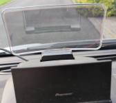
Remove 2 torx screws to get plastic cover over instrument binacle off.
Remove connector from bottom of HUD
Remove 3 screw’s holding HUD to binacle cover
Remove multiple small Philips screws and remove base plate of HUD
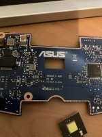
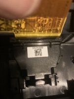
Remove several screws holding ASUS PCB in place
Flick white lock on PCB that secures the flexible cable from the projector then remove the PCB disconnect small 2 pin connector with RED and BLACK wires supplying the projector LED.
Now you can access the projector assy
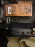
Remove screws holding projector assy to HUD body.
You will then see the red and black power supply wires connected to the faulty PCB with the LED
Remove the heatsink from the projector assy 2 screws.
Then remove the heatsink pad (blue silicon type material)
Now you can see 2 small countersunk screws flush that hold the LED PCB to the projector body.
Remove screws and LED PCB. Desolder the Red and Black wires from the LED PCB and solder onto the replacement LED PCB.
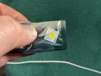
The original PCB has a square 7mm by 7mm LED that fits in a recess in the projector body.
The new one is round 7mm diameter so won’t sit in. Just place it centrally over the recess then put a new double sided heat sink pad on the heatsink and fit the heatsink in place with the 2 screws this will trap the LED roughly centralised to the recess. Couldn’t find a suitable 7mm square LED so the only option was the round one. Not a perfect solution but it works.
Re assemble in reverse. Be careful when refitting the flexi lead from the projector to the ASUS PCB and close the white lock to secure.
Sorry don’t have good photos of the job. Not sure how confident you are doing this type of work?
Maybe I could talk you through it on a teams call or take mine apart and send more pictures.
I would recommend an anti static wrist band when handling the components just to be sure.
Best of luck
Jim