thats not arc thats RobW lol 


arc said:bielstein sell a tuning package for the Cinq, and that photo is of the manifold they use. Rob said it looked like a std FIAT part, so thought the best people to ask would be in the panda section
edit: guessing that manifold would be found on an Uno too?
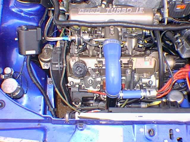
arc said:the painted manifold is my cinq manifold yeah. also the same one used on the punto60 engine i had.
its odd to see it on fuel injected punto.
does the uno one have room for a water temperature sensor? not a big problem, but bit of a faff to re-add one if its not there!
arc said:well the std one on the cinq is..erm crap!
on the cinq, there is a temp sender on the head for the gauge and then a sender in the inlet manifold for the ECU. Gauge one isnt needed, but the ECU one is!
Hopefully get one of the other types of manifolds, and Rob is gonna get them on a flowbench to compare the two.
I am thinking of slowly building up my parts mountain and it would be a shame to miss out on this if it does actually improve flow. Or if its not worth doing then i'll save the skin on my knuckles for another job. balidey said:And another aside, probably a bit too technical but i'll ask anyway. When working out optimum inlet lengths you measure to the ends of the err... shall we say 'Trumpet', but where is this point on the SPI throttle body? Is it to the very top edge, where its very wide where the air box bolts on, or does the theoretical dimension end at a point further in the TB where the bore is much smaller and closer to the manifold diameter? Reason is i am wanting to work out what happens to the shock wave pulses, for a completely different project.
arseofbox said:I designed inlet manifolds for a petrol engine for my 3rd uni project (last year). In all of the models I took the inlet tract length as being from the point the inlet physically starts (say the end of a resonant volume like an airbox) and where it finishes (the head-manifold flange joint)
If you know what youre handling, OId recommend anaylsing it in some capable CFD software like Ansys for example, but bear in mind that its very complicated and it won't necessarily work without dyno-proving.
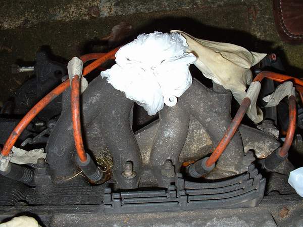
arc said:Look closely at this, anyone recognise what engine it is off?

notice the way it differs to this manifold:
http://tackycheese.net/gallery/main.php?g2_view=core.ShowItem&g2_itemId=5626
guessing it's off a carb'd FIRE engine, but i know nothing about them. anyone help?
the charger will be wet as the injector stack will be on the airbox side of charger to help atomise fuel further.