Tuning MOD'S and ROCKERS!

Currently reading:
Tuning MOD'S and ROCKERS!

Joined
Dec 27, 2014
Messages
1,133
Points
363
Location
Ripon
Greetings All, Apologies to those who don't know, this thread has nothing to do with Skin Heads and Teddy Boy's.
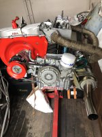
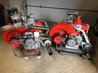
A brief update regarding my two engines as I'm dancing the engine Hokey - Cokey a swap from the Hot to the Not so hot engine!!! This is the first time I have had the chance to get them together complete and ready to run.
IMG_1515.JPG
IMG_1515.JPG The one on the left is the fully balanced job with a 40/80-80/40 cam and a c/r of 10.5:1 with Solex twin choke. The one on the right is the 'not-so-hot job' with 35/75-75/35 cam and a c/r of 9.8:1 using a weber 30 DGF (32bhp at the wheels@5000rpm) it also has a complete 'Bambino' fan housing, but that said I never want to rebuild one of these again - Nightmare !!!
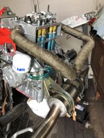
The principle reason for removing the 'Hot' engine is to carry out a few upgrades and Mod's, the head will have 35mm inlet valves fitted and I have treated myself (Christmas + B
IMG_1507.JPG
IMG_1507.JPG
IMG_1526.JPG
IMG_1526.JPG
IMG_1527.JPG
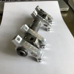
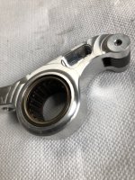
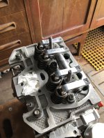
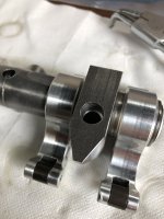
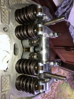
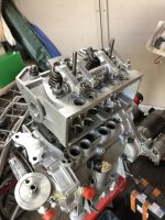
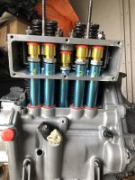
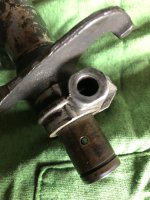
IMG_1527.JPGirthday) to a neat Rocker Roller set from DMD. Having made some lengthy research into the basic valve function I have found that roller rockers can release wasted output by keeping the valve stem from excessive contact with the internal wall of the valve guide. Even though there is oil involved it does not fully remove the friction caused by the action of the rocker arm on the valve top. Essentially the vale rocks from side to side against the guide, roller rockers ensure that the valve moves straight up and down and with a bearing on the rocker shaft there is little movement friction of the rocker on a plain shaft. The rockers themselves are constructed from 'Ergal' Alloy which is a 7075 Alloy used in aircraft parts having good ductility, resistance to fatigue and high strength - tough all round. The rollers should minimise tappet noise too. I had the rocker rail apart recently and have found a very high construction level with all parts well made. The final pic shows the rail on the head, but this is only for illustration as the rockers and steel mounts all need to be accurately shimmed for spacing and height, I may have to have another set of pushrods cut to suit this application anyway!
IMG_1515.JPG
 
Greetings All, I thought that I would make a start on getting the new rocker shaft adjusted onto the valve stems, a simple enough job thought I - it turned out to be anything but! The first job was to drill a 10mm relief 7mm deep into the bottom of both steel shaft supports, it seems that the maker assumed that an 8mm hole would do, But, with later heads the studs are 10mm in the head and taper down to 8mm above the head, the relief was to accommodate the 10mm to 8mm taper otherwise the posts would not sit flat on the head.
So
IMG_1528.JPG
IMG_1529.JPG
IMG_1529.JPG
IMG_1530.JPG
essentially the roller initially needs to be in central contact with the valve, sorting out the position of the individual rockers proved time consuming as to move the rockers along the shaft either way involved multiple disassembly and reassembly to move individual shims the correct amount. The supplied shims were 0.05mm thick and thinking that the adjustment could be fiddly I also ordered some 0.01mm shims to adjust out any slack on the shaft. The main problem was remembering how many shims were where and checking that the addition or subtraction of the shim position made the required adjustment. o_Oo_Oo_O
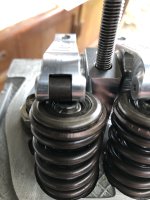
Suffice to say it took a while!!!!! The pics show the out of position and final in position of the rollers. The next job is to determine the contact patch of the roller on the top of the valve, this may involve shimming under the support posts and cutting the pushrods too. Later.
Ian.IMG_1528.JPGIMG_1529.JPGIMG_1530.JPG
 
Greetings All, I thought that I would make a start on getting the new rocker shaft adjusted onto the valve stems, a simple enough job thought I - it turned out to be anything but! The first job was to drill a 10mm relief 7mm deep into the bottom of both steel shaft supports, it seems that the maker assumed that an 8mm hole would do, But, with later heads the studs are 10mm in the head and taper down to 8mm above the head, the relief was to accommodate the 10mm to 8mm taper otherwise the posts would not sit flat on the head.
So View attachment 420230View attachment 420231View attachment 420231View attachment 420233essentially the roller initially needs to be in central contact with the valve, sorting out the position of the individual rockers proved time consuming as to move the rockers along the shaft either way involved multiple disassembly and reassembly to move individual shims the correct amount. The supplied shims were 0.05mm thick and thinking that the adjustment could be fiddly I also ordered some 0.01mm shims to adjust out any slack on the shaft. The main problem was remembering how many shims were where and checking that the addition or subtraction of the shim position made the required adjustment. o_Oo_Oo_O
Suffice to say it took a while!!!!! The pics show the out of position and final in position of the rollers. The next job is to determine the contact patch of the roller on the top of the valve, this may involve shimming under the support posts and cutting the pushrods too. Later.
Ian.View attachment 420230View attachment 420231View attachment 420233
That looks, and sounds, to be very 'interesting' (!) installation Ian. If I remember correctly, the rockers should be at 90 deg to the valve-stem at "1/2 cam lift" with a minimum of 25thou between the coils of the valve spring at full valve-lift. There should also be no more than 3 threads of the tappet-adjuster showing under the rocker (and into the top of the pushrod). I have a very interesting article on this subject---I will send you a copy of it if you so wish.
 
Hi Tom, yes I have that article you refer to, I am working through the items quoted in it, but need to establish the roller pattern on the top of the valve stem first. This will require full assembly and adjustment of the valves and then I have to turn over the engine several times to mark the valve stem. I do have a little problem to solve first as when fitting the oil feed pipe the rocker shaft does not seat fully ( it does with the other shaft) The valve adjustment must be carried out with the feeler gauge moving sideways across the roller not front to back as the roller can pull in a thicker gauge and give an improper measurement. There will be some critical numbers to work out later as the rocker ratio is 1.55:1 and could cause spring binding at full lift (I note that Abarth used a ratio of 1.564:1 (in 1964)) and I still don't know if I will need to shim the shaft supports or cut a new set of push rods ????? Later.
Ian.
 
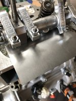
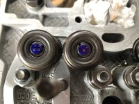
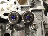
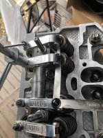
Greetings, I continued with the job of determining the roller pattern on the top of the valve stem, you have to mark the top of each stem with a pen and then reassemble - once everything is back together the engine is turned over a few times to enable the tell-tale mark to be made. Unfortunately I don't have a good marker so the resulting tell-tale is less than perfect. However, after removing the rocker assembly it was clear that the rollers are off to one side which means that the support posts will have to be shimmed to increase their height and thus move the pattern over to the centre of the valve, the pics don't show what the naked eye can see, but give a rough idea of the situation. To add to the situation I resolved to check the valve stem - rocker arm relationship, this should be a 90deg angle at the setting of half of valve lift. Problem, my dial gauge has a magnetic base and the head is alloy so I found a scrap of thin metal and bolted that onto the top head surface the fix gave a good solid base for the gauge assembly to sit on. The resulting angle was a tad off to my old eyes so that's a job for the professionals, it will probably mean that another set of pushrod tubes will have to be cut!!!!!!! My next job is to manufacture the correct shims for the post height. Later.
Ian.
IMG_1534.JPG
IMG_1535.JPG
IMG_1532.JPG
IMG_1533.JPG
 
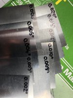
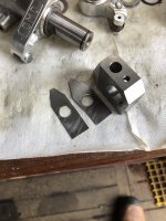
Greetings All, The shim set arrived late from Ebay so hence the delay in posting! The sheet thickness runs from 2 thou up to 20 thou and they are large enough to give me a few tries at getting things right. I decided to line up everything in an approximate fashion and took a guess that I would need 2 x 20thou shims to start with. The resulting finish was rather rough but they fitted and did the job. Unfortunately the given contact patch was as bad as the first attempt, but did show that the roller position had moved toward the inlet side of the head over the valve stem. But, it's still not enough to my eye notwithstanding the bad marker I shall have to make up another set at 10thou and check again. All this is moving the rocker angle away from the 90deg it should be, so I shall have to sacrifice another set of new pushrods - I will check to see if a full size set will cut the mustard anyway!!! Later.
Ian.
IMG_1538.JPG
IMG_1537.JPGIMG_1538.JPG
IMG_1541.JPG
IMG_1541.JPG
IMG_1537.JPG
 
Greetings All, well I've cut another set of shims at 10thou - they don't look pretty, but do the job. success! With a total of 30thou shimmed under the rocker posts the roller tips now sit in the middle of the valve tips. The resulting marking is indistinct in the pictures but using a caliper I determined that the correct position had been arrived at. If I'm honest I could have gone on with a shim of 2thou to be pedantic, but cutting the hole into something that thin is tricky, at least with 10 and 20 thou shims the material is thick enough to withstand drilling - carefully!!! Anyway it will give my engineer something to check himself while the engine is in his care. I now have to check the rocker arm angle against the valve stem (90deg) at half of cam lift with an uncut set of pushrods to see what result I get. To cut or not to cut that is the question:oops::oops::oops: Later.
Ian.
IMG_1546.JPG
IMG_1546.JPG
IMG_1547.JPG
IMG_1547.JPG
 
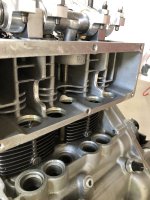
It's Back!!!!! after a while with my engine man the engine has returned to my little shed. The work centered on the change of inlet valves up to 35 from 34mm + new stem seals, but included work on the head webs on the pushrod side to allow adjustment of the VW pushrod tubes. At the same time the new roller rockers needed very careful adjustment to get the desired geometry correct. So I can confirm now that using the new set of pushrods (uncut) another 20 thou of shim was required under the steel rail supports to get the rollers onto the centre of the valve stems. With the valve adjusters set at the mid point all of the rockers are now horizontal at half of cam lift, and the clearance between the spring cap and the stem seals has been adjusted to allow maximum lift without any contact. The valves springs are not binding at max lift.
I have to clean and reassemble the pushrod tubes and I'll check the head gasket too. My engine man reported very slight signs of detonation mainly in the number two cylinder so I shall have to go up one stage on the main jets in the short term prior to getting a rolling road test, I'll continue with the rebuild later.
Ian.
IMG_1577.JPG
IMG_1577.JPG
IMG_1578.JPG
IMG_1578.JPG
 
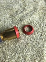
So, the first lesson here is that if you use a great deal of silicone sealant to fix a possible leak don't expect it to hold and don't complain when you have to remove the mess after!!! :mad::mad::mad: After cleaning the pushrod tubes (VW type) I set about using the set of beefy seals that came with them. Made sure the head and pistons were clean and carefully assembled the lot - this time with the tubes the other way up. A slight chamfer on the underside of the top location helped locate the top seal. Then after torquing the head down set the tubes up tight with the intent of finishing the job after they have settled overnight. Then it's setting the rockers. Later.
Ian.
IMG_1579.JPG
IMG_1579.JPG
IMG_1580.JPG
IMG_1580.JPG
 
So, before final fitting of the rocker assembly everything had to come apart and sit in an oil bath for a while, this is to ensure that the rollers were fully lubricated with engine oil prior to fitting as you cannot depend on the engine supply being sufficient fast enough during the first start, it's all a bit messy but worth it in the end.
Setting the valve tappet gap (lash) is completed with the feeler gauge fed across the roller not into and under the roller because the roller will tend to feed the gauge under and give an incorrect gapping. The gap settings are standard. More cleaning to do before the alternator/fan housing goes back on, Later.
Ian.
IMG_1581.JPG
IMG_1581.JPG
 
So, cleaning the fan housing didn't go too bad essentially a hose off with petrol and wipe down while holding ones breath:oops::oops: the replacement was a bit of a faff because I was fitting rubber seals against the head to ensure good airflow at the same time. I know I'm getting on, and it's a sod when you think something you need is where you left it only to find that it's not, then having to hunt high and low - the missing part was a small adaptor I made up to connect the spin-on filter adaptor to the return on the crankcase and it took a full half hour on my knees to locate it. It's going somewhere more obvious next time!!! Replacing the exhaust system was another trial, funny how an item can be so simply removed and yet be so fiddly to get back on - I nearly lost the will:mad::mad::mad: Anyway it's on and the next job is to assemble the engine run stand in preparation for the leak test, later.
Ian.
IMG_1586.JPG
IMG_1586.JPG
IMG_1587.JPG
IMG_1587.JPG
 
So, after a fill of my favourite Mobil 1 10w60 I spun the engine over a few times and made sure that I had oil in view from the spin-on filter, plugs in and switches on - ignition and hey presto after a couple of turns with the Solex choke on away she went.
Oil pressure good and charging well, I do think it's running a tad rich, after the main jet change, but I'm not overly concerned as the rolling road will sort the jetting. Allowed the temperature to rise while checking for leaks around the pushrod tubes and after finding no leakage got the thermostat housing fitted. Two further runs to get everything settled in with no problems were completed and I am aware that the roller rockers are much quieter in operation than standard, although the timing gear set I have used does give off some gear noise it's not as bad as it was. So time to strip all the run stand off and hump it into the car, later.
Ian.
IMG_1607.JPG

 
OK update, there has been a slight delay regarding the visit to the rolling road mainly due to the need for a modification to the modification???? Engine complete and all buttoned up, no leaks and starting well - time for a test drive. Everything up to temperature and ............... what's that slight rattle on lift off - not there before - home!!! I know these engines have form with the noises they can make, the only thing it can be is the rockers methinks, So get the rocker rail off and check for evidence of problems and ......... nothing! :(:(:( what's going on then? I did notice the lubrication holes were a tad small so I had a rummage through my bit's box to find a original rocker assembly and made a comparison - blimey!! The original lubrication holes are 3mm and apart from the delivery hole go all the way through the tube. Not so with the new roller rockers, delivery hole 2mm rocker lube holes 1mm and only on one side????
I decided to err on the safe side and get the holes opened up and all the way through as per the original fitment. My main concern was the need for plenty of oil getting to the rockers at high rpm and if the factory says 3mm then I'm with them. My engineer did have a slight problem drilling the tube as it's very hard material, but came up with carbide tipped drill bits that managed to effect the 3mm holes!!! Time to reassemble the lot remembering where all the shims went, :unsure::unsure::unsure: more later.
Ian.

IMG_1643.JPG
IMG_1643.JPG
IMG_1644.JPG
IMG_1645.JPG
IMG_1646.JPG
 
Seems a sensible thing to do, shame it’s delayed you.

Is it possible that the new shaft had smaller oil feed holes as the needle roller bearings in the new rockers require a smaller quantity of oil to operate safely than the plain bushes in the standard rockers?
 
Back
Top