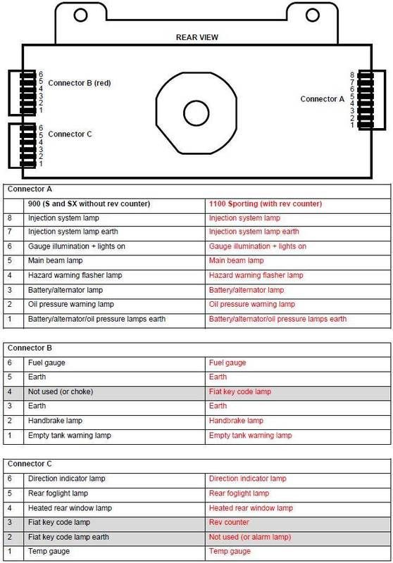
I have just completed this mod (thanks to the above) and would like to add a postscript. The Fiat key code lamp is sacrificed when adding the rev counter so I worked out how to retain this function. Below is the connector wiring for the printed circuit board (pcb) behind the gauges. Only 3 differences in the connector wiring (highlighted in grey). I used the pin numbering and alphabetic connector designation used in the Haynes manual. The circuit diagram in the manual is the early Cinq (with choke).
The changes I made to the above are as follows:
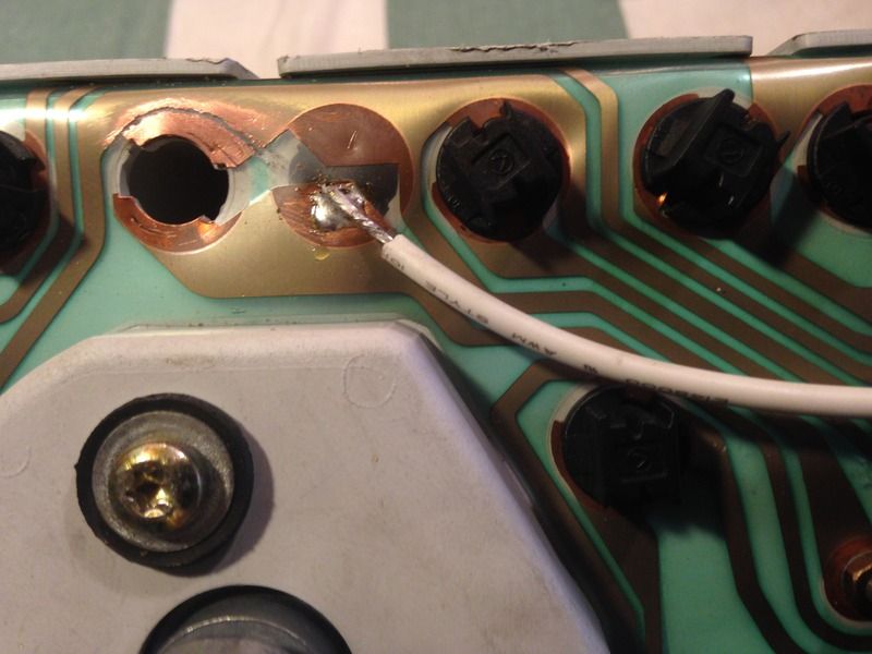
1. Instead of soldering the rev counter feed wire (from pin 23 of the ECU) to the pcb, cut the blue/black wire that goes to pin 3 on connector C leaving a few centimeters on the connector. Then connect the rev counter feed wire to this short length of wire.
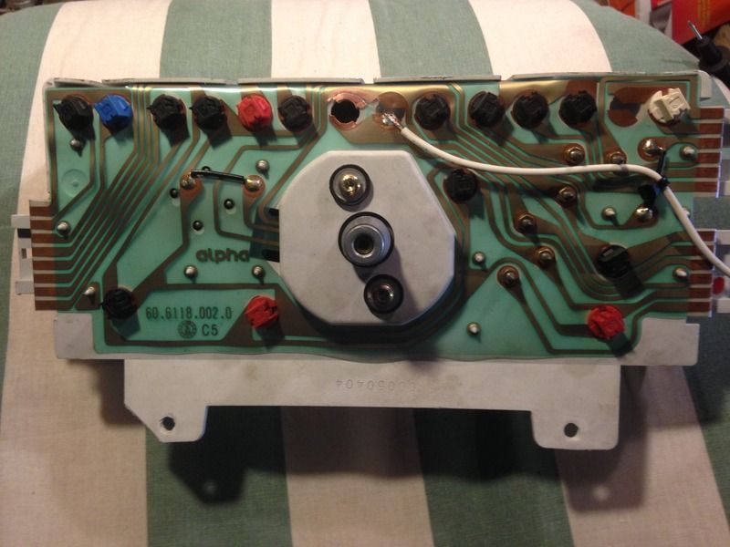
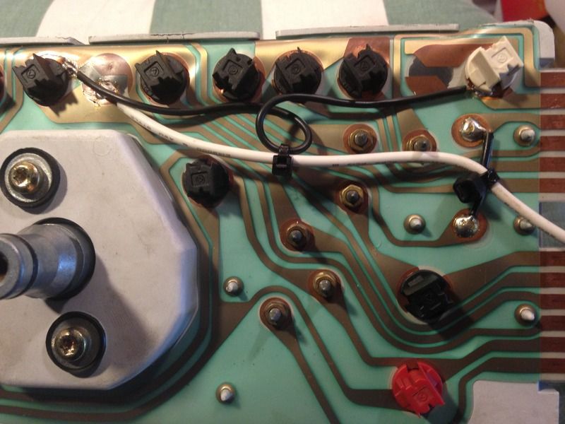
2. The other lose end of the blue/black wire (Fiat key code) needs to be connected to the Fiat key code indicator lamp on the rev counter pcb by soldering a wire (white in this example) to the copper area as shown below. This wire is connected to the blue/black wire in the loom using a bullet or spade connector.
The earth for the Fiat key code lamp needs to go to pin 2 of connector C. To do this, the copper area around the Fiat key code lamp on the pcb has to be isolated as shown below. VERY CAREFULLY scratch the copper from the flexible green substrate with a sharp knife. Be extremely careful not to cut through this material. Check (with a continuity tester or ohm meter) that the copper is isolated from the earth connection around it. Leave enough free copper to make a solder joint - outside the area occupied by the bulb holder.
Solder a wire (black in this example) to the freshly isolated copper area and solder the other end to the unused lamp position that leads to pin 2 on connector C. Ensure that solder does not bridge the isolated area - check with the continuity tester again. This forms the earth connection for the Fiat key code. Note that the white bulb holder is a dummy as this indicator position is not used:
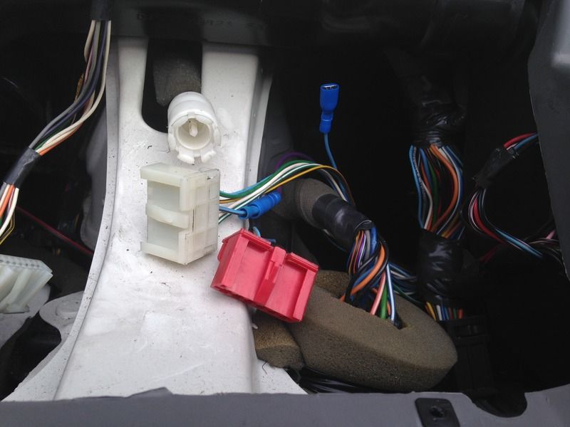
The photo below shows where the blue/black wire is cut and how the rev counter feed connection from pin 23 on the ECU (purple in this example) is made. I picked up the connection from the purple/black wire on the Fuel pump relay (as in the guide above).
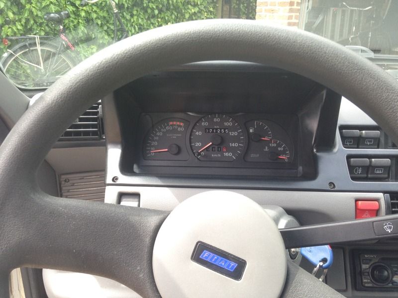
I also replaced the Sporting's 180 km/h speedo with my 160km/h speedo from my original gauge set. Simple one-to-one swap. And don't forget to check all the lamps - two were blown on mine - as it's much easier to change them now!
Maybe a lot of work for a lamp that flashes on for a fraction a second when you start the car, but I wanted the conversion to be complete.
Note that wire colours might vary and only try this if you are confident with fine soldering. Too much heat may lift the copper from the green substrate or melt the plastic case behind.
I cannot accept responsibility if it goes wrong!