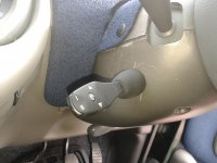
I finished fitting my cruise control today and must say am very pleased with the result. My car is a 2003 ELX JTD 115
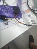
I bought an AP900 system from BridgeWater electronics but the same system can be had form a good many other traders. It comes in a nice kit however the supposed "Plug and Play" T connector that is meant to T into the Accelerator Position Sensor and the ECU harness is incorrect certainly for the 98-2004 models. It may well be right for the facelift models but neither the supplier nor the manufacturer could confirm this. As such, not wanting to cut the original car wires to manually bride in the system I made my own harness. I managed to get a second hand sensor along with both plugs from a breakers, cut off the sensor and just used the plugs. I cut off the plugs from the supplied harness and replaced them with the second hand ones.
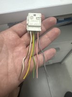
Now to create the harness you need to know what the signals coming to and from the ECU are. As I mentioned in a previous post the documentation in the DTE and the E-Learn is seriously misleading. The pinouts shown on the plugs are wrong and the colour codings given are in Italian even though the body of the text is in english. If you are to undertake this this you must do some serious due diligence before starting the job.
Tips
The plug config from the ECU to the TPS has 6 pins and they are number (looking from the back of the plug where the wires come in
2----------1
6 5 4 3
Pinouts are
1 = Signal
2 = +VE
3 = -VE
4 = Signal
5 = +VE
6 = -VE
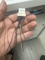
The TPS has 2 x potentiometers a primary and a back up. Pins 1,2,3 are for the primary and 4,5,6 the secondary
Once you have have created the harness the rest is straight forward and just follow the instructions. Brown and White to brake switch, purple to clutch switch and green to earth.
You need to connect the system to speed sensor and RPM sensor. I took these from the back of the speedo cluster. On mine there are two plugs a smaller black one and a larger grey one. The grey one is Plug A and pin 5 (Brown/Yellow) is VSS (goes to Blue on the CC) whilst pin 6 is RPM (White) (goes to Yellow on the CC)
Once down you have to do some electronic systems setting to tell it to recognise the brake pedal, throttle position and speed settings. Done !!
I bought an AP900 system from BridgeWater electronics but the same system can be had form a good many other traders. It comes in a nice kit however the supposed "Plug and Play" T connector that is meant to T into the Accelerator Position Sensor and the ECU harness is incorrect certainly for the 98-2004 models. It may well be right for the facelift models but neither the supplier nor the manufacturer could confirm this. As such, not wanting to cut the original car wires to manually bride in the system I made my own harness. I managed to get a second hand sensor along with both plugs from a breakers, cut off the sensor and just used the plugs. I cut off the plugs from the supplied harness and replaced them with the second hand ones.
Now to create the harness you need to know what the signals coming to and from the ECU are. As I mentioned in a previous post the documentation in the DTE and the E-Learn is seriously misleading. The pinouts shown on the plugs are wrong and the colour codings given are in Italian even though the body of the text is in english. If you are to undertake this this you must do some serious due diligence before starting the job.
Tips
The plug config from the ECU to the TPS has 6 pins and they are number (looking from the back of the plug where the wires come in
2----------1
6 5 4 3
Pinouts are
1 = Signal
2 = +VE
3 = -VE
4 = Signal
5 = +VE
6 = -VE
The TPS has 2 x potentiometers a primary and a back up. Pins 1,2,3 are for the primary and 4,5,6 the secondary
Once you have have created the harness the rest is straight forward and just follow the instructions. Brown and White to brake switch, purple to clutch switch and green to earth.
You need to connect the system to speed sensor and RPM sensor. I took these from the back of the speedo cluster. On mine there are two plugs a smaller black one and a larger grey one. The grey one is Plug A and pin 5 (Brown/Yellow) is VSS (goes to Blue on the CC) whilst pin 6 is RPM (White) (goes to Yellow on the CC)
Once down you have to do some electronic systems setting to tell it to recognise the brake pedal, throttle position and speed settings. Done !!
Last edited: