

Like many, I would like to retrofit a cruise control in my van. It's a 2007 Jumper/Relay from Citroen but it has the 3.0 Iveco so the ECU is identical to its Italian twin afaik.
I was a bit shocked as I saw the pricing of some aftermarket products, but after digging into elearn it seems that fitting a cruise control is only a matter of getting 4 wires to the ECU.

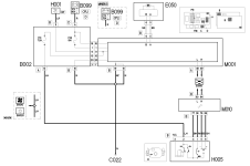
If I understood correctly I just have to
- install a switch providing 12V (from pin 2 connector B fuse F51) to pin 77 on the ECU to enable cruise control
- install 3 push button switches to 38 for resume, pin 78 to decrease speed and pin 56 to increase speed.
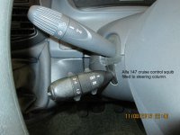
I could get a stalk from the scrapyard or from a compatible model (Croma?) or just build my own.
Is it really that simple (well, apart from getting all the wiring in and to the ECU) and where can I get the right pins for the ECU connector?
I was a bit shocked as I saw the pricing of some aftermarket products, but after digging into elearn it seems that fitting a cruise control is only a matter of getting 4 wires to the ECU.
If I understood correctly I just have to
- install a switch providing 12V (from pin 2 connector B fuse F51) to pin 77 on the ECU to enable cruise control
- install 3 push button switches to 38 for resume, pin 78 to decrease speed and pin 56 to increase speed.
I could get a stalk from the scrapyard or from a compatible model (Croma?) or just build my own.
Is it really that simple (well, apart from getting all the wiring in and to the ECU) and where can I get the right pins for the ECU connector?
- Model
- 3.0
- Year
- 2007
") In the Panda 2020 1.0 GSE Hybrid / Body / CAN Setup Proxi Alignment Procedure (2014+) / Adjustments.
In the Panda 2020 1.0 GSE Hybrid / Body / CAN Setup Proxi Alignment Procedure (2014+) / Adjustments.