Here's what eLearn says about central locking:
The simultaneous operation of the door locks takes place via:
- the remote control;
- the key inserted in the catch on the driver''s door;
- the locking/unlocking button in the centre console.
The remote control unit has 3 buttons that allow the operation of the central locking system: a button for unlocking the doors, one for locking the vehicle and one for releasing the boot
The door unlocking/locking management strategy is carried out by the Body Computer which controls the effective status of the locks by means of the signals that arrive from the switches in the actual locks and the key pawl (only drive''s door). in this way, the "locking" command is only carried out if all the doors are properly shut and the locks unlocked; conversely, the "unlocking" command is only carried out if the locks are locked;
The locks have an additional motor that carries out the dead lock function which allows the interior door opening handles to be mechanically disconnected so that it is no longer possible to open the door from the inside (for example, after having broken the glass in a theft attempt); the dead lock function also inhibits the operation of the door locking/unlocking buttons in the dashboard.
The dead lock function is switched on at the time the doors are locked or by pressing the remote control twice.
A LED on the door lock/release key on the facia emits the following signals:
- locking of the locks: the LED lights up for 3 seconds. If some of the doors or the boot are not properly shut at the time when the locks are locked, the LED flashes at 3 Hz for 3 seconds;
- dead lock activation: the LED flashes twice for 0.5 seconds;
- unlocking the locks: the LED goes out.
The instrument panel acquires the door status signal via the CAN and lights up the "doors open" warning light and, at the same time, the information is shown on the display; in addition, if one of the doors or the boot or the bonnet is open and the speed of the vehicle exceeds around 4 km/h, an acoustic warning is also emitted.
The boot unlocking operating mode can be selected still using the special setup in the instrument panel:
- assisted boot unlocking: the tailgate is considered as a fifth door to all intents and purposes;
- indepedent boot unlocking: the boot is locked when the doors are locked, whilst it can be unlocked independently of the unlocking of the doors.
The doors are automatically unlocked if the inertia switch is operated: the instrument panel receives a signal from the switch, lights up the appropriate warning light and notifies the Body Computer via the CAN.
The door lock motors are protected by a special fuse on the Body Computer.
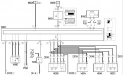
FUNCTIONAL DESCRIPTION
The door lock/release function is controlled by Body Computer M1.
Body Computer M1 receives the following input:
- lock/release signals from the aerial-receiver of remote control unit P93, which are connected to pins 1 and 2 of connector K of M1;
- lock/release signals from the key pawl located in lock N50, at pin 29 of connector A of M1;
- the negative signal from the lock/release button, located in control unit H90, at pin 39 of connector D of M1; a reference earth reaches pin 5 of H90 from pin 49 of connector D.
Body Computer M1 - connector G - is supplied directly from the battery from a line protected by maxifuse F2 of engine compartment control unit B1. It is supplied by an ignition-operated supply (INT) at pin 32 of connector D; pin 10 of connector H of M1 provides the Body Computer with a reference earth.
According to the control logic illustrated, Body Computer M1 controls the geared motors for the door locks: the joint power supply for the motors is sent from pin 19 of connector E; the locking/unlocking motors (B/S) are operated from pin 17 of connector E; the dead lock motors (DL) for locks N50 and N51 are operated from pin 18 of connector E.
The signal LED in control unit H90 is turned on by a signal from pin 1 of connector D of M1.
The activation of the inertia switch I50 is indicated at pin 23 of connector A of the Body Computer M1 : this signal, as described previously, causes the opening of the doors.
Body Computer M1 is connected via the CAN line to instrument panel E50, to which it sends a signal that turns on the door open warning light, where necessary, and activates the buzzer to give an acoustic signal.
BRs, Bernie
If someone here helped You fix -or better, understand- your issue, hit the thanks icon @ bottom right corner, it's free and makes us feel helpy ;-)


") . My guess is that yours has been replaced OR you get a "continental" car ? How is the switch in the Passenger door (or can you central lock from it) ?
. My guess is that yours has been replaced OR you get a "continental" car ? How is the switch in the Passenger door (or can you central lock from it) ?