Technical Automatic Box 2003 LHD Ducato 2.8jtd

Currently reading:
Technical Automatic Box 2003 LHD Ducato 2.8jtd

motion32

New member
Joined
Apr 12, 2016
Messages
2
Points
1
:confused:
I have an 2003 Arto 69GL Automatic.
She was UK supplied when new (Marquis Motorhomes) and ordered as LHD for continental touring by first owner.

Automatic Gearbox has decided to go into LIMP HOME mode. The first problem was the inability to move the gear lever from Park. Using the mechanical by-pass I can get the gears although only in 3rd gear as limp home mode in activated.
I am a retired Auto Electrician so thought I would look at the Solenoid release for the Gear Lever having ruled out the brake switch. When I removed the cover around the gear lever I found a 7 way connector loosely lying in the area and a PC board which amongst other functions drives the solenoid BUT with no wiring to it. It seems as though the 7 pin connector has broken free and I am unable to re-connect it.

I have tried unsucessfuly to get a wiring diagram for the base vehicle Ducato 2.8gtd. Tried my local Fiat dealer who could not help and wondered if anyone is able to supply a wiring diagram as with that I will be able to hard wire the PC Board which is most probably the reason for the ECU taking its action.
Any help most welcome, thanks
Dave
 
Hi Welcome to the forum
The WSM for the 2.8JTD X244 is available in the forums download section -
https://www.fiatforum.com/downloads.php?do=download&downloadid=439
It is an ISO image split in 5 parts which when extracted out produce a single file which is then burnt to a CD producing the eLearn Workshop Manual. Also see the Guide for downloading & burning the eLearn to CD -
https://www.fiatforum.com/miscellan...nloading-burning-244-elearn-iso-cd-image.html
As far as I know there is no mention of the Auto Gearbox in the eLearn Manual as here in Australia it was fitted as a "Kit" by "Dealers" to special orders. The gearbox is a variant of a ZF 4HP20 Transmission used in numerous FWD vehicles.
Attached is a Citroen Training manual & another PDF if they are any use, Chapter 16 in the training one has a fault finding section.
There have been a couple of posts on here about similar problems with the ZF auto & they were traced back to the Multifunction switch on the front of the transmission but as you say yours probably relates to the connector near the gear lever. No wiring diagrams unfortunately.
Cheers
 

Attachments

  • ZF4_HP20_AUTO_training[1].pdf
    3.6 MB · Views: 163
  • ZF_4HP20_Gangwechselmuster.pdf
    38.8 KB · Views: 134
It may be that even if you were able to get a wiring diagram the PC board would not be shown in component level but just as a 'black box' with the wiring loom leading to it.

The clue should be in the actual connector; is this in two parts? If so the male part may have broken away from the board and close inspection may reveal stubs of wire which should match the stubs in the bottom of the connector.

If not it may be an edge connector where slots in the tabs connect to soldered areas on the board and just needs pushing back on.

If you could post photos someone with computer experience might have some suggestions.
 

Events Team

Join the team
Psst! Are you free August the 2nd??

Then come and join us at FIATs and Friends.

Held at the British Motor Museum, there will be loads to see and do so there's no excuse not to be there 😜

Sign up using the link above to register yourself for our stand - everyone is welcome!
6021678366
 
If its a removable connector there will be something like this on the board.
1830718-40.jpg


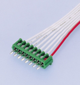
However it looks like a board insertion connector thats soldered into the board like this:
da.jpg


If its an board insertion type thats sheared off, I would first figure out why.
They are quite sturdy it would take a lot of repetitive cycles to break it off or a hard shearing force.
If it was mine I would solder the wires direct to the board and then reinforce with hot glue, and secure the free wire with cable ties to provide strain relief.

If you really wanted to replace the connector measure the pitch between the pins and look on the Japanese Solderless Terminals or Molex sites for the match.
 
Last edited:
FANTASTIC
I cannot believe that I had such a great reply THANKS.
Your Photo's are exactly as my PC Boards and Connectors. Still cannot see how my connector was ever on the Solenoid Driver Board (have 30 years experience of electronics and connectors but not seen anything like this one) HOWEVER the best thing is I can see the wire colours and layout. Wanted to hard wire but could not work out left to right or vice versa for the colours but from your pictures can clearly see. THANKS so much. Will wire up and re-fit tomorrow and let you know if it worked.
P.S
When I bought the vehicle a year ago the last owners said he had a problem moving from Park and a Frech mechanic had greased it and it was a bit better. I always found moving from park stiff/difficult. Maybe the "mechanic" had somehow got the cable caught up or something, anyway I can now try the above.
Dave
 
Back
Top