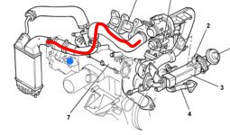
In trying to remove the fuel pressure regulator from the high pressure pump I’ve discovered my van is the EGR version, contrary to what I said above. I don’t think this impacts on my current non starting issue except that it is making access to the pressure regulator more difficult. On the attached photo the pressure regulator is the blue blob and the red pipe is part of the EGR circuit which is something (else) I know nothing about. My question is; can I just remove these pipes to improve access to the regulator?


You are using an out of date browser. It may not display this or other websites correctly.
You should upgrade or use an alternative browser.
You should upgrade or use an alternative browser.
Technical 2005 2.3jtd starting issue
- Thread starter ChasF
- Start date
Currently reading:
Technical 2005 2.3jtd starting issue
Communicator
Prominent member
- Joined
- Aug 3, 2019
- Messages
- 3,494
- Points
- 954
EGR under certain conditions, takes a portion of the exhaust gas, cools it,and recycles it into the engine, to reduce overall emmissions.. As long as you are not dealing with the cooler, I see no reason why you should not remove the pipe to improve access. The pipe will of course need reinstating on reassembly, and there may be joint gaskets involved.
Thanks for the information Cmmnicator.
The new pressure regulator turned up today and I’ve fitted it but still no go. I’m now thinking that the pressure regulator not opening is an ecu fault.
There are 2 new issues: when fitting the new fpr I fond a lose wire with a connector which has been dislodged from somewhere but can’t find where and secondly the engine management light now stays on when cranking the engine over - it didn’t before.
Communicator
Prominent member
- Joined
- Aug 3, 2019
- Messages
- 3,494
- Points
- 954
My commiserations as regards the pressure regulator.
I have no experience of doing it, but is it not possible to command the regulator via Multiecuscan? Perhaps try with the old one first.
The loose connector is probably for an unfitted option e.g. engine oil level. I also have a loose connector in my engine bay. I seem to remember confirming that the colours matched those for an oil level gauge. On my correted drawing I have 3 pin connector. Pin 1 yellow/green, pin 2 empty, pin 3 brown/orange, but drawing originally showed plain orange on pin 3.
My commiserations as regards the pressure regulator.
I have no experience of doing it, but is it not possible to command the regulator via Multiecuscan? Perhaps try with the old one first.
The loose connector is probably for an unfitted option e.g. engine oil level. I also have a loose connector in my engine bay. I seem to remember confirming that the colours matched those for an oil level gauge. On my correted drawing I have 3 pin connector. Pin 1 yellow/green, pin 2 empty, pin 3 brown/orange, but drawing originally showed plain orange on pin 3.
I have tested the fuel pressure regulator using the MultiECUscan ‘actuator’ facility and it clicks as it says it should. I assume this is testing the fpr, wiring and some of the ecu. I’ve also found some stored codes two of which had turned on the engine management light but I’ve cleared these, the light has gone off and they don’t reappear when I crank the engine over, however the fuel pressure regulator still doesn’t open. I’ve also monitored the fuel pressure sensor voltage and the rail pressure neither of which change when the engine is cranked.
I’ve read the elearn fuel system info which describes how the fuel pressure sensor controls the regulator when the engine is running but doesn’t explain how it should work at starting. As far as I can determine if the cam sensor or fuel pressure sensor were to blame there should be some codes.
So once again, no idea where to go from here.
The loose wire is just a single with a proper waterproof socket on it - it’s probably not anything important. I have another spare cable under the air filter but that has a blanking plug fitted.
By way of an update my van is still sitting in my barn as a non starter. I have not done much work as it is very cold at the moment but I have been trawling for information. Much of the information is misleading and there are a number of known errors in the elearn files, however I have read through the troubleshooting sequence for a non starting engine and will be measuring the low pressure fuel line pressure and putting the scope on the crank sensor, possibly checking the cmp/cnp timing with a view to eliminating these as possible faults. It seems the fpr operates in bypass which explains why it does not open when there is no rail pressure. It has been suggested that the lack of rail pressure could be a stuck injector or a faulty pressure relief valve. Now elearn shows the pressure release valve on the end of the rail and the pressure sensor in the middle but in reality the sensor is on the end and I can’t find the prv - there may not be one? I’m not sure how to test for an open injector or the prv if it exists other than by replacement. Once I’ve eliminated these items it seems I will have no choice but to fit a new pump, if it doesn’t go then it’s a new ECU.
Does anyone have a pinout for the ECU as the one shown in elearn is unreadable
Does anyone have a pinout for the ECU as the one shown in elearn is unreadable
Communicator
Prominent member
- Joined
- Aug 3, 2019
- Messages
- 3,494
- Points
- 954
If I am understanding your use of "pinout" correctly, then at least I can help with that as it is the same for both 2.3jtd and 2.8jtd engines.
Please see attached file which which was sourced from the diagrams section of eLearn. The corrections are mine, and if they do not make sense please inform me.
Please see attached file which which was sourced from the diagrams section of eLearn. The corrections are mine, and if they do not make sense please inform me.
Attachments
Communicator
Prominent member
- Joined
- Aug 3, 2019
- Messages
- 3,494
- Points
- 954
I think that the above post made today on an alternative thread by @bugsymike is very appropriate here as well. I have taken the liberty of marking the most appropriate section in italics.Someone may correct me, but I believe once primed by the low pressure pump in the fuel tank , the high pressure pump will draw the fuel as it needs.
I actually had an 03 Doblo 1.9 non turbo that didn't have a tank pump fitted at all. It had a different fault which I was able to test for by running a can of fuel on the wing with the high pressure pump sucking it directly. The fault it proved was an air leak on the plastic connection of the flow and return fuel pipes. Not relevant in your case.
If not already done, I would advise a "leak off test" at the injectors on your engine to measure if any injector leaks too much in to the leak off return to the fuel tank. This is done by connecting four plastic bottles, one to each return from the injectors so you can measure exactly how much is "leaking " past each injector pintle body.
It only wants one dodgy injector to leak too much and it shuts the whole engine down on a common rail design, unlike the old days where it was possible for one injector pipe to be hanging off and the engine could still run ( badly) on three cylinders.
This maybe the reason you have no/low line pressure reading rather than a dodgy sensor.
If I am understanding your use of "pinout" correctly, then at least I can help with that as it is the same for both 2.3jtd and 2.8jtd engines.
Please see attached file which which was sourced from the diagrams section of eLearn. The corrections are mine, and if they do not make sense please inform me.
Thanks for the pinout and I can see why you’ve made the changes. The problem I have is the wiring diagram on the eLearn fuel system document (which is the only one I can find) is very low resolution and the pin nos. from the sensors/actuators where they connect to the ECU are unreadable.
I will try the leak off test on the injectors after I determined if there is a pressure relief valve on the rail and it’s not leaking. Again, the diagram on the eLearn showing the main components of the fuel system shows a pipe from the prv on the rail connecting to a junction block on the flow and return pipes to the hp pump. On my van I definitely don’t have this pipe I just have a spigot on the junction block which doesn’t look as if it’s had a pipe fitted to it - what is going on? 90% of this job is working out what is what and getting reliable information, it seems.
Communicator
Prominent member
- Joined
- Aug 3, 2019
- Messages
- 3,494
- Points
- 954
Thanks for the pinout and I can see why you’ve made the changes. The problem I have is the wiring diagram on the eLearn fuel system document (which is the only one I can find) is very low resolution and the pin nos. from the sensors/actuators where they connect to the ECU are unreadable.
I will try the leak off test on the injectors after I determined if there is a pressure relief valve on the rail and it’s not leaking. Again, the diagram on the eLearn showing the main components of the fuel system shows a pipe from the prv on the rail connecting to a junction block on the flow and return pipes to the hp pump. On my van I definitely don’t have this pipe I just have a spigot on the junction block which doesn’t look as if it’s had a pipe fitted to it - what is going on? 90% of this job is working out what is what and getting reliable information, it seems.
Chas,
Please see attached custom tweaked files. I have made 2 pdf files which I hope will cover your engine. Please let me know if they help, and that I have not been wasting my time.
Attachments
Chas,
Please see attached custom tweaked files. I have made 2 pdf files which I hope will cover your engine. Please let me know if they help, and that I have not been wasting my time.
Thanks for these, they look like just the job.
I need to get the pressure and leak tests done first. Wish I could find this prv.
Communicator
Prominent member
- Joined
- Aug 3, 2019
- Messages
- 3,494
- Points
- 954
Chas,
I should have checked before. Does your vehicle have the UFI fuel filter (black plastic on my 2.8jtd) or does it have the metal canister type? There is a difference in the diagrams, or at least sheet 1, as I have designated the LH section of the two diagrams.
I am begining to question whether there is any subtle difference between the diagrams for the 2.3jtd, and those for the 2.8jtd, as they look very similar. If identical, I could have saved myself some effort.
Communicator
Prominent member
- Joined
- Aug 3, 2019
- Messages
- 3,494
- Points
- 954
Chas,Thanks for these, they look like just the job.
I need to get the pressure and leak tests done first. Wish I could find this prv.
Perhaps have a look at this photo. Is that not the PRV at RHS of photo, with bolt for banjo pipe connector back to lp system?
Chas,
Perhaps have a look at this photo. Is that not the PRV at RHS of photo, with bolt for banjo pipe connector back to lp system?
Sorry only just seen this! The photo shows the rail as it is on the eLearn diagram but on mine the pressure sensor is fitted in place of the prv and there is no centre tapping where the pressure sensor is shown.
I’ve still to measure a couple of things and then I’ll be stripping it down to get better access to the rail and hp pump.
I’ve just been out to confirm what I said above. I’ve disconnected the injector wiring and pulled the plastic trunking back to get a better view and check there are no connections on the rear of the rail and there are only the 4 injector pipes, the feed from the pump and the pressure sensor on the end. The leak off tube from the injectors goes back to the pump but there doesn’t seem to be a return pipe from the rail.

This show the air pressure sensor on the right hand end of the rail

Middle of the rail no tapping for the prv

Left end of the rail - the open plug is the camshaft sensor
This show the air pressure sensor on the right hand end of the rail
Middle of the rail no tapping for the prv
Left end of the rail - the open plug is the camshaft sensor
Well, after a lot of mucking about and a quick knee replacement operation in the middle, I had to conclude that it was the diesel high pressure pump that had failed. I received the refurbed pump this morning and it’s now all done with a new cam belt etc. and was finally able to drive it out into the sunshine. We’ll be off on our holidays on Monday.
Thanks for all the help.
Thanks for all the help.
Similar threads
- Replies
- 0
- Views
- 221
- Replies
- 1
- Views
- 444