Hello,
This is my first post on the Fiat Forum - although I'm a frequent spectator and very appreciative of the help I have obtained in the last few years from you guys for my 2003 Stilo 1.2.
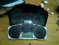
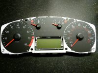
Like a lot of others have posted here, I too have a Fiat Stilo with a faulty instrument cluster.
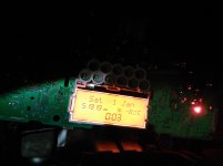
The cluster instruments are dead except that the LCD screen glows orange.
I have checked the fuses F37 and F53 but with no success, so I removed the cluster (thank you so much to the previous posters for the guide on how to do this !).
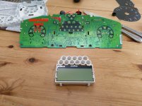
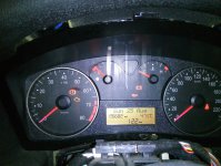
I removed the cluser from it's plastic housing and then reconnected it to the D connector on the wiring loom so it's getting power.
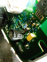
The LCD screen still glows orange as before but I have noticed that if I move the large capacitor on the back of the board (220 microfarad circled in the photo) some lights on the cluster (such as the green headlight symbol) illuminate temporarily.
This leads me to suspect that there is a bad solder joint somewhere in the region of that capacitor on the board.
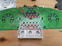
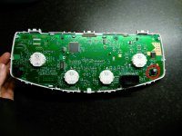
My problem is that to get at the soldered side of the board I need to remove black faceplate and the needles from the gauges.
Does anyone know if there is a safe enough way to do this without destroying the instruments ?
Or is attempting this myself a recipe for disaster ?
Many Thanks.
Enda
This is my first post on the Fiat Forum - although I'm a frequent spectator and very appreciative of the help I have obtained in the last few years from you guys for my 2003 Stilo 1.2.
Like a lot of others have posted here, I too have a Fiat Stilo with a faulty instrument cluster.
The cluster instruments are dead except that the LCD screen glows orange.
I have checked the fuses F37 and F53 but with no success, so I removed the cluster (thank you so much to the previous posters for the guide on how to do this !).
I removed the cluser from it's plastic housing and then reconnected it to the D connector on the wiring loom so it's getting power.
The LCD screen still glows orange as before but I have noticed that if I move the large capacitor on the back of the board (220 microfarad circled in the photo) some lights on the cluster (such as the green headlight symbol) illuminate temporarily.
This leads me to suspect that there is a bad solder joint somewhere in the region of that capacitor on the board.
My problem is that to get at the soldered side of the board I need to remove black faceplate and the needles from the gauges.
Does anyone know if there is a safe enough way to do this without destroying the instruments ?
Or is attempting this myself a recipe for disaster ?
Many Thanks.
Enda
Attachments
Last edited: