

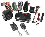
Sniper X2 Alarm & No “door open” leads
I imagine most Puntos that needed an alarm are already fitted with one now so I am not too sure quite whether this will be useful to too many. However, after suffering what clearly should have been a one day home job, expand out into 3 days, I thought it would be good to share the solution. The Sniper X2 is a fully function packed system and was somewhat of an overkill on what I wanted. Installation proved significantly less than straightforward.
 However, many thanks to all the wonderful posters on this site
 I was able to gather information to help me solve the various problems posed. In response to their kind efforts, I add my little contribution.
Problem 1
Fundamentally, against all the evidence I could find on this site, my Feb 2003 Punto was missing wires to pinout 1 – left hand door open switch and pinout 11 - right hand door open switch.

Problem 2
Problem 1 was also compounded by the fact that the sniper X2 did not like the way voltage decayed on lines to a stable 2.0 Volts, long term, which would then drop to zero on opening – e.g. 36 – boot open switch and 8 & 25 door lock – open signal. This generated the problem that when the immobilizer was armed, all was well but then, after about 3 or 4 seconds voltages on these lines dropped from c. 5.00 volts to 2.00 volts and then the alarm sounded indicating that the doors/tailgate were open. Once this had happened the Sniper then ignores any other change in status to these triggers, ie no more security is available should the doors or tailgate be opened sometime later.
Problem 3
Wiring the immobilizer itself was not straightforward due to the “installation” book having contents in contradiction to the title.
 Sniper obviously use the “help line” at 50p per minute as a major revenue stream rather than the manufacture and sale of alarms. When both the Central Locking and Indicators were wired as instructed – nothing whatsoever happens.

Problem 4
My Punto had no load space light, but the computer (dash display) could detect the tailgate being open, when the ignition was on. So there had to be a switch somewhere that could be used as part of the alarm system.
Overview
The Sniper X2 has more features than I need and definitely did not fulfill my very clear requirement at time of purchase – it must have sensible and clear instructions on installation.
Needed
2 stage shock/impact alarm, 3 bleeps if knocked, full alarm to sound if jolts continue – ie if forced entry being made – warn thieves away before they gain entry to the car.
Ultrasonic detection – more for their visual deterrent effect
Both doors to be triggered
Bonnet to be triggered
Tailgate to be triggered
LED – go chose another Punto pal – this owner has learnt the hard way
Now all that seemed quite easy based on the fact that the car already had warning lights showing if the tail-gate or doors were open when the ignition was on.
Execution
Problem 4 – went to the scrappy and got a loadspace light. Don’t spend 2 hours extracting all the relevant wiring and switches like I did.
 This was some mad product plan scheme by Fiat. Behind the carpet all the stuff is there, it is just the 10p plastic moulding and bulb that they left out. A 60 second job to connect up and fit.
Problem 1 & 2
Front Doors
I think with a more basic alarm you can use pinouts 8, 25 & 36 for the door & tailgate triggers. 8 and 25, would have replaced the missing leads to pins 1 and 11 on my car (recommended in many places on this site) as both go to zero volts when the door is opened. These were useless with the Sniper X2, as it read their 2.0 V when closed, as zero ! So instead I went for 21 the courtesy lamp time timer control (drops from 12.00 to 0.00 V when either of the doors are opened).
Tailgate
It was incredible frustrating that A36 proved useless. I tried it on its own without the doors but at 2.00V the Sniper went into alarm mode every time even though the tailgate was firmly closed ! I had to run a lead from the alarm to tee into the lead that runs from the load-space light to the boot lock – Grey black. The most convenient place for this was just under the LH rear tail-light cluster. It is easy to run a lead from the alarm, alongside the main harness on the LH sill all the way back. No need to go in into the tailgate.
Since I was using a single trigger input to the Sniper (W3-0 Door trigger input –ve), it is necessary to put 2 diodes into this lead at the alarm. Then run 1 lead, from 1 diode to pinout A21 and from the other diode to the grey balck lead from the loadspace light. The alarm seems to put enough initial voltage into the terminal, when arming, so that when either line goes to ground, it can sense the change in potential.
Leave W3-1 unconnected.
Problem 3
As recommended on this site by many others,the use either of pinouts 17 or 24 for door lock “Release”, and either of pinouts 34 or 35 for “lock” are fine. However to get something to happen using the Sniper X2, you also need to provide the Sniper with a 12V positive supply to both W8-3 pink and W8-6 orange. In the alarm installation manual these are somewhat unhelpfully called “Door Lock no”. Don’t believe it!
[ I also soldered leads W8-1 black to W8-4 white “Door lock nc”, as I think this was the other side of internal switching in the alarm (but not sure if that was entirely necessary)]. The 12 v supply to W8-3 and W8-6 needs a separate fuse so if a fault develops it takes out just the alarm central locking and not the whole alarm system. Basically I was following some elements of Diagram #3 which states “central locking with a door motor being required”. You do not need a door lock motor!
To get the hazards to flash, information on this site is good – I used pinouts 3 and 12 – indicator lamp rear left/right. Again, absolutely nothing happens once you connect to these using the Sniper. Put another fused 12.0 V supply into W2-1 [instruction manual - “To ground or +12V depending on polarity of W2-2(+/-)”] and the indicators function properly.
Other fitments are the same as more basic alarms.
Now it is all functioning – it appears super. But the hours spent sorting it all made a modest little project turn out longer than an engine swap !
Terminal conections for Sniper X2 (Feb 2003 Active Sport - 2 door, 8 valve)
W1 – plug in 2 way transceiver
W2-1 +12V fused supply(1)
W2-1- - A3 and A12
W2-3 – to negative Earth (1)
W2-4 – to +12V (ignition supply Ignition switch B3)
W2-5 - +12V fused supply(2)
W2-6 – Siren output (Other wire from siren to Earth)
W2-7 – not connected
W2-8 – to relay terminal 85
W3-0 – via diode to A21
Via diode to H/N lead from boot light
W3-1 - not connected
W3-2 - not connected
W3-3 - not connected
W3-4 - not connected
W3-5 - not connected
W3-6 - not connected
W3-7 - not connected
W3-8 – Bonnet switch (to be fitted as part of kit)
W3-9 - not connected
W4- Plug-in LED connector
W5 Plug in valet switch
W6 – 1/4 - terminal block from ultrasonic sensors
W7 – 1/4 - terminal block from shock sensor
W8-1 – solder to W8-4
W8-2 – A34 or A35
W8-3 - +12V fused supply(3), common with W8-6
W8-4 – solder to W8-1
W8-5 – to A17 or A24
W8-6 - +12V fused supply(3), common with W8-3
Body Computer connector A
1 Left hand door open switch - Absent
2 Left side indicator repeater lamp - Pink white
3 Right rear indicator lamp - Pink
4 Fuel level sensor (+) - Grey
5 Left tail lamp - Grey red
6 Right tail lamp - Yellow red
7 Alarm sensor serial line - Absent
8 Left front door lock - open signal - Brown Green
9 Not connected
10 Autoclose serial line (may be for electric windows) - Absent
11 Right hand door open switch - Absent
12 Left rear indicator lamp - Pink white
13 Right side indicator repeater lamp - Pink
14 Handbrake "on" switch - Pink black
15 Fuel level sensor (-) - White black
16 Left rear door lock - open signal
17 Right front door lock - release signal - Lt Blue black
18 K-line aggregate 3 - Absent
19 Not connected
20 Not connected
21 Courtesy lamp timer control - Lt Blue yellow
22 Right hand brake lamp - Green yellow
23 Courtesy lamp supply - Red orange (Yellow ?)
24 Left front door lock - release signal - Lt blue purple
25 Right front door lock - open signal - Grey brown
26 Left rear door lock - open signal
27 Alarm sensor supply - Absent
28 Not connected
29 Not connected
30 Not connected
31 Left rear fog lamp - Grey
32 Left hand brake lamp - Green white
33 Boot lamp supply - Red green
34 Left front door lock - locking signal - White green
35 Right front door lock - locking signal - White black
36 Boot open switch - Grey black
37 Not connected
38 Not connected
39 Not connected
40 Not connected
I imagine most Puntos that needed an alarm are already fitted with one now so I am not too sure quite whether this will be useful to too many. However, after suffering what clearly should have been a one day home job, expand out into 3 days, I thought it would be good to share the solution. The Sniper X2 is a fully function packed system and was somewhat of an overkill on what I wanted. Installation proved significantly less than straightforward.
Problem 1
Fundamentally, against all the evidence I could find on this site, my Feb 2003 Punto was missing wires to pinout 1 – left hand door open switch and pinout 11 - right hand door open switch.
Problem 2
Problem 1 was also compounded by the fact that the sniper X2 did not like the way voltage decayed on lines to a stable 2.0 Volts, long term, which would then drop to zero on opening – e.g. 36 – boot open switch and 8 & 25 door lock – open signal. This generated the problem that when the immobilizer was armed, all was well but then, after about 3 or 4 seconds voltages on these lines dropped from c. 5.00 volts to 2.00 volts and then the alarm sounded indicating that the doors/tailgate were open. Once this had happened the Sniper then ignores any other change in status to these triggers, ie no more security is available should the doors or tailgate be opened sometime later.
Problem 3
Wiring the immobilizer itself was not straightforward due to the “installation” book having contents in contradiction to the title.
Problem 4
My Punto had no load space light, but the computer (dash display) could detect the tailgate being open, when the ignition was on. So there had to be a switch somewhere that could be used as part of the alarm system.
Overview
The Sniper X2 has more features than I need and definitely did not fulfill my very clear requirement at time of purchase – it must have sensible and clear instructions on installation.
Needed
2 stage shock/impact alarm, 3 bleeps if knocked, full alarm to sound if jolts continue – ie if forced entry being made – warn thieves away before they gain entry to the car.
Ultrasonic detection – more for their visual deterrent effect
Both doors to be triggered
Bonnet to be triggered
Tailgate to be triggered
LED – go chose another Punto pal – this owner has learnt the hard way
Now all that seemed quite easy based on the fact that the car already had warning lights showing if the tail-gate or doors were open when the ignition was on.
Execution
Problem 4 – went to the scrappy and got a loadspace light. Don’t spend 2 hours extracting all the relevant wiring and switches like I did.
Problem 1 & 2
Front Doors
I think with a more basic alarm you can use pinouts 8, 25 & 36 for the door & tailgate triggers. 8 and 25, would have replaced the missing leads to pins 1 and 11 on my car (recommended in many places on this site) as both go to zero volts when the door is opened. These were useless with the Sniper X2, as it read their 2.0 V when closed, as zero ! So instead I went for 21 the courtesy lamp time timer control (drops from 12.00 to 0.00 V when either of the doors are opened).
Tailgate
It was incredible frustrating that A36 proved useless. I tried it on its own without the doors but at 2.00V the Sniper went into alarm mode every time even though the tailgate was firmly closed ! I had to run a lead from the alarm to tee into the lead that runs from the load-space light to the boot lock – Grey black. The most convenient place for this was just under the LH rear tail-light cluster. It is easy to run a lead from the alarm, alongside the main harness on the LH sill all the way back. No need to go in into the tailgate.
Since I was using a single trigger input to the Sniper (W3-0 Door trigger input –ve), it is necessary to put 2 diodes into this lead at the alarm. Then run 1 lead, from 1 diode to pinout A21 and from the other diode to the grey balck lead from the loadspace light. The alarm seems to put enough initial voltage into the terminal, when arming, so that when either line goes to ground, it can sense the change in potential.
Leave W3-1 unconnected.
Problem 3
As recommended on this site by many others,the use either of pinouts 17 or 24 for door lock “Release”, and either of pinouts 34 or 35 for “lock” are fine. However to get something to happen using the Sniper X2, you also need to provide the Sniper with a 12V positive supply to both W8-3 pink and W8-6 orange. In the alarm installation manual these are somewhat unhelpfully called “Door Lock no”. Don’t believe it!
To get the hazards to flash, information on this site is good – I used pinouts 3 and 12 – indicator lamp rear left/right. Again, absolutely nothing happens once you connect to these using the Sniper. Put another fused 12.0 V supply into W2-1 [instruction manual - “To ground or +12V depending on polarity of W2-2(+/-)”] and the indicators function properly.
Other fitments are the same as more basic alarms.
Now it is all functioning – it appears super. But the hours spent sorting it all made a modest little project turn out longer than an engine swap !
Terminal conections for Sniper X2 (Feb 2003 Active Sport - 2 door, 8 valve)
W1 – plug in 2 way transceiver
W2-1 +12V fused supply(1)
W2-1- - A3 and A12
W2-3 – to negative Earth (1)
W2-4 – to +12V (ignition supply Ignition switch B3)
W2-5 - +12V fused supply(2)
W2-6 – Siren output (Other wire from siren to Earth)
W2-7 – not connected
W2-8 – to relay terminal 85
W3-0 – via diode to A21
Via diode to H/N lead from boot light
W3-1 - not connected
W3-2 - not connected
W3-3 - not connected
W3-4 - not connected
W3-5 - not connected
W3-6 - not connected
W3-7 - not connected
W3-8 – Bonnet switch (to be fitted as part of kit)
W3-9 - not connected
W4- Plug-in LED connector
W5 Plug in valet switch
W6 – 1/4 - terminal block from ultrasonic sensors
W7 – 1/4 - terminal block from shock sensor
W8-1 – solder to W8-4
W8-2 – A34 or A35
W8-3 - +12V fused supply(3), common with W8-6
W8-4 – solder to W8-1
W8-5 – to A17 or A24
W8-6 - +12V fused supply(3), common with W8-3
Body Computer connector A
1 Left hand door open switch - Absent
2 Left side indicator repeater lamp - Pink white
3 Right rear indicator lamp - Pink
4 Fuel level sensor (+) - Grey
5 Left tail lamp - Grey red
6 Right tail lamp - Yellow red
7 Alarm sensor serial line - Absent
8 Left front door lock - open signal - Brown Green
9 Not connected
10 Autoclose serial line (may be for electric windows) - Absent
11 Right hand door open switch - Absent
12 Left rear indicator lamp - Pink white
13 Right side indicator repeater lamp - Pink
14 Handbrake "on" switch - Pink black
15 Fuel level sensor (-) - White black
16 Left rear door lock - open signal
17 Right front door lock - release signal - Lt Blue black
18 K-line aggregate 3 - Absent
19 Not connected
20 Not connected
21 Courtesy lamp timer control - Lt Blue yellow
22 Right hand brake lamp - Green yellow
23 Courtesy lamp supply - Red orange (Yellow ?)
24 Left front door lock - release signal - Lt blue purple
25 Right front door lock - open signal - Grey brown
26 Left rear door lock - open signal
27 Alarm sensor supply - Absent
28 Not connected
29 Not connected
30 Not connected
31 Left rear fog lamp - Grey
32 Left hand brake lamp - Green white
33 Boot lamp supply - Red green
34 Left front door lock - locking signal - White green
35 Right front door lock - locking signal - White black
36 Boot open switch - Grey black
37 Not connected
38 Not connected
39 Not connected
40 Not connected