Not had much time to work on the Multi recently, but did a bit more last Saturday.
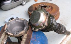
Hubs: Not at all happy with the quality of the Birth ones, so set about sniffing out proper Fiat ones on the cheap. Gratuitous piccy:

I think the part numbers are just about readable for both. The OEM ones are spot on and a very nice fit for the J&R CV's.
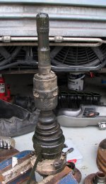
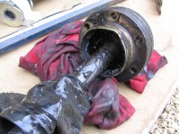
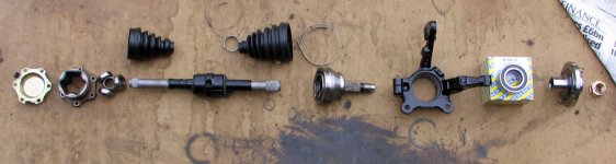
Then it was on to the halfshafts. Offside one first. Part assembled, to give an idea of what goes in to one:

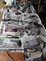
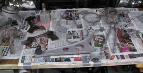
Slide the gaiters well on to the shaft to get them out of the way while you get the CV's in place. I took a bit more time to lay out all of the bits for the nearside shaft,
to give a better idea of order of assembly. Purdy. Shame it's out of focus:

Early days, but I'm impressed by the epoxy Rustbuster paint. Feels very tough. Will be interesting to see how it stands up to a winter on Britain's finest roads.
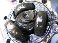
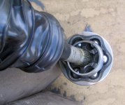
Assembly as for the OS. Slide the gaiters on to the driveshaft. I found that pulling the gaiter right back on itself made it a lot easier to see what I'm doing when
wrestling the new CV joint into place, like this:

You can just about see the ends of the retaining clip in the shadow of the little cut-out in the back of the CV joint. Sliding it into place is a lot easier if you give
the driveshaft splines (and the corresponding ones in the CV) a good smear of grease. A few light taps on the end of the stub shaft (at the other end of the CV)
with a rubber mallet and it soon clicks into place.
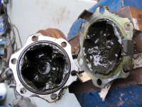
There then follows a particularly filthy session with a tube of CV grease. No photos of this I'm afraid as I wanted the camera to work afterwards
")
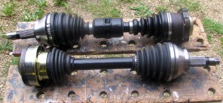
. Once all
cleaned up and the gaiter clips crimped, these are ready to go back on:

I also whipped the steering rack off. That's off to Kiley Clinton tomorrow for a rebuild. It was rebuilt by a bunch in Bristol 3 years ago but has now got some
play in the OS which isn't to my liking. Won't be going back to those shysters as I reckon they did little more than spray it black and fit new boots
.
Kiley Clinton get a lot of good reviews on the web so I hold out more hope this time around. While I was in there and had done all the hard work, it seemed rude
not to abuse the privilege:

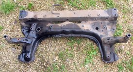
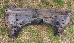
Took it down the road to have it shotblasted this morning
. Looks to be in very good nick actually - just some surface rust on the underside where the
main pressings meet the box section that runs across the back.

Looking forward to getting this back all cleaned up and ready for some more Rustbuster lovin'. Will need to spray the internals with a can of Dinitrol and a wand
I think.