Disclaimer - Please note that this is a guide only and I take NO responsibility for any damaged caused to yourself or vehicle whilst using this guide. If you are unsure how to do something leave it to the professionals. I followed the below operation and everything worked fine in my case.
I have managed to retrofit ESP on my 2006 1.3MTJ 90hp Dualogic. The main reason I started this project was for safety and for the hill holder assist. This is how me and my dad did it:
You can then sell your old abs and steering column to get back some money.
Before starting test to see if the led for ESP in the instrument cluster is present by using Multiecuscan. Select dashboard computer, Actuators and ESP control light.
Parts required:
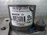
1. ESP hydraulic unit pump. I paid €35 pounds on ebay
This will replace the old ABS Pump
The pump was from an GP 1.4 Sport (there are more compatibles)
The code on it :
BOSCH 51787092 0 265 234 512
Fiat part number : 71746431 (been substituted 71746362)
There are many ESP units that are compatible. The problem is the there is no Fiat part number on the units only Bosch. The Bosch automotive catalog vehicle search, web site is of great help you fill in the details and it will show units that are compatible with your car. ( View vehicle equipment then select suspension. In Eper Abs units that have ESP will have the 392 code VDC.
From photos you can tell if the unit has ESP as it is written on the sticker on the pump and also from the 2 large inlet pipes that are in the middle of the pump and not on the sides. That’s why you also need new brake pipes.
2. Hydraulic Unit bracket. Fiat part number: 51841910
3. New brake pipe between ESP unit and brake cylinder, designed for ESP. Fiat part number :51796558 and 51855955 price €16+€21.
4. YAW Sensor €20 from ebay
There are many Yaw units that are compatible as long as it is from Grande Punto
Bosch 55701951
5. Connector to the yaw rate sensor, Part number 1-967616-1 TE Connectivity AMP
Buy from Mouser part number 571-1-967616-1
Farnell amp 1-967616-1 housing micro quadlok connectors 4mm 6way 1556972
Transfer Multisort Elektronik TME 1-967616-1 connectors: 962885-1
Can also buy from Saab spare parts 5241278
6 cable shoes to the yaw rate sensor, Part number 962885-1 TE Connectivity
AMP plus another 2 Brake unit plug Saab part no. 5351747
7. Steering Column with position Angle Sensor ESP/VDC €130 from ebay
There are many Steering units that are compatible as long as it is from Grande Punto. Very important the steering column must have steering position sensor. You can easily tell by looking at the photos of the units. The ones with the steering angle sensor (for ESP/VDC) will have a blue, purple or orange colored sheath from the torque sensor cables that connect to the steering ECU. They will also have 7 cables. The one with no steering angle sensor (No ESP/VDC) will have white or yellow and only 6 cables. There is also a newer version in which the torque sensor connection is made inside the unit. There is no sheath visible. The only way to tell if it is for (ESP/VDC) is by taking the Fiat part number and searching in Eper. If it shows the 392 VDC code and when you click on the item 2Y which is Grande Punto then it should work. The one I got was the newer ones.
Fiat part number: 51860332
New switch panel with ASR disconnect button.
Canbus wire buy from VW Part No. 000 979 987 Cost €25 for 10m.
Adhesive 19mmx15M Cloth Fabric Tape to make looms from ebay for €2
Elearn drawings, ESP E7023, ABS (to see difference from one another) Canbus E1050, Steering.
Electric installation
For connecting wire I do not like to use wire taps I think they are not safe. I prefer remove the insulation from the wire spread the wire strands making a hole in the middle then twist the new wire in the middle cover with self amalgamating tape and then wrap fabric tape.
ABS M050 Connector ASR disconnect button to ESP connector
This is not really necessary as it is only to disconnect the ASR in certain conditions and the ESP can work without this connection.
Make a loom with 2 cables. Remove the radio then unplug the connector from the switch panel and look at the pins 15 and 6 they should be there. Remove the side plastic near the pedals and look for intermediate coupling connector D020A those 2 cable terminate on the multi plug. On cars that came with ESP the two wire continue to the ESP ECU plug. You can also remove the ABS plug cut the cable tie remove the plug cover and check if the wire are there (21 and 22).
Switch panel plug

From the intermediate coupling we need to tap the two wire 12 and 13 the colors should be blue/red and Grey/brown. Install a new wiring harness unit. These wire then need to go through the firewall to the ESP hydraulic unit plug and inserted into the plug location 21 and 22.
Intermediate coupling connector D020A


ABS Plug Pins


YAW sensor K074
It's mounted under the parking brake, you have to remove parking brake center console. And side panels. The carpet comes precut from factory


Earth

The yaw sensor needs 12v positive and a negative. For the 12v I got the power from by removing plug H on the body computer and adding a connector in position 16 on the plug. You can also just tap wire 21 on the plug since connector 16 is connected to connector 21 inside the Body computer (Connector 21 supplies the ABS computer with power). Any ignition switched 12v power supply should work by adding and inline 7.5A fuse. For the ground there is a screw bolted to the chassis right near where the yaw sensor is located.
Make a wire loom with 2 set of can bus wire plus 1 12v wire if getting your power from Body computer, The wire loom should go from near the body computer to the Yaw Sensor near hand brake. Label one set of the Can bus wire CAN Hi CAN LO ESP/ABS M050 on both ends of the loom and the other set CAN Hi CAN LO Steering M086.
Connect
12V -------- -> K074 (pin 01)
Negative -> K74 (pin 06)
CAN Hi ABS M050 -> K074 (pin 05)
CAN Lo ABS M050 -> K074 (pin 03)
CAN Hi Ster. M086 -> K074 (pin 04)
CAN Lo Ster. M086 -> K074 (pin 02)
Move the green lock connector to side to insert the connectors

Steering Column M086
For the steering column replacement follow one of the guides that is available in the forum.
You can test the column before removing the old one. Just disconnect the power supply and data connector (do no disconnect the torque sensor cable) and connect it to the new column. Then using Alfaodb or Multiecuscan check if it is working and if the column is showing around near + - 0º. Also if the Steering column position sensor is present. (DO NOT start engine when testing the new column in this configuration) This can also probably be done with the new ABS ECU.
Once the new Column is in position remove the data connector from the steering column we will now need to rearrange how the can wire are connected.

The old connection is the CAN signals Hi/Lo come from the ABS pump to steering column to connect pins 2 and 3 then leave on pins 7 and 8
The new connection will be CAN signals Hi/Lo come from the ABS pump to Yaw senor then leave yaw sensor to connect to steering column on pins 2 and 3
You can cut the can wire on the plug PIN 2 and 3. Leave about 1.5cm to be able to solder the other wires. (ONLY CUT after confirming the pin location on the plug, it is written on the plug and on elearn. The wire colors for CAN lines were wrong on elearn for my car so CONFRIM pin location) I preferred to remove the pins from the connectors and connect the CAN HI/Lo steering directly on the connectors. If you solder add heat shrink.
CAN Hi Ster. M086 -> K074 (pin 03)
CAN Lo Ster. M086 -> K074 (pin 02)

Next solder the cut CAN wires coming from the ABS to the yaw sensor wires (CAN Hi CAN LO ESP/ABS M050).
Repairs to CAN bus wiring
When repairs are performed, both bus wires must have the same length. When the wires (1) and (2) are twisted, the length of each complete twist must be 20 mm (A).
There must not be any section of untwisted wiring longer than (B) = 50 mm, for example in the vicinity of welded joints.
Replace the hydraulic unit with one with ESP-function
To replace the hydraulic unit remove the old one with the bracket. To connect the new one first attach it to the new bracket then position it in to place. Do not tighten it. I had to move it to be able to tighten the pipes. (BE VERY CAREFUL when tightening the brake pipes, first tighten by hand so as not to cross thread. The ABS body is aluminum and very easy to cross thread. I also had to remove the pipes from some of their support brackets to be able to tighten them.
Also don't forget to bleed the brakes.
Surprises after installation.
1. Connected Multiecuscan went to body computer and to read errors:
U1711 - Automatic Transmission (NCA-NCR)
U1706 - Brake system (NFR)
U1702 - Electric Steering (NGE)
U1701 - Engine control (NCM)
U0001 - C-CAN
U0426 – Minicrypt
U1726 - Airbag Node (NAB)
Plus Christmas tree lights all on.
I tried to clear the fault codes but they all came back on. OK, I thought I have damaged the car big time. It was around 21H so I left the car and thought, ok tomorrow is another day. Next morning I remembered I had forgotten to connect the earth cable under the ABS unit. Connected it but still had errors. More trouble shooting. Decided to re check wiring, Bingo! Found the problem. I had told my dad to solder the wrong can bus wires.
He soldered the CAN HI from the ABS to the Can Lo going to the Yaw sensor and Can Lo to Can Hi. Corrected the wires and I was able to do proxy alignment.
I still had many error codes. I took over 3 weeks to be able to clear them all out.
Gearbox Dualogic CFC300
1: P290F - Side Acceler./Yaw Node (NYL)
The longitudinal acceleration signal learn operation must be performed
Longitudinal acceleration signal learn
I took a long time to figure what this error was until I found training manual on the internet for the Ducato M40 Dualogic gearbox with the following:
Yaw sensor learning
The procedure follows the guidelines shown below:
Cases in which it should be carried out:
- Replacing the gearbox control unit
- Replacing longitudinal acceleration sensor (NYR)
Reasons why it should be carried out:
The following procedure is used to learn the longitudinal acceleration set-off value transmitted by
the NYR.
Failure to execute the procedure impairs system operation. This procedure must therefore be run
at the end of line and in service.
The problem was that in Multiecuscan for the 1.3MTJ CFC300 gearbox there is no procedure for the “longitudinal acceleration sensor learn” I tiered to select the 1.4 engine which uses the CFC328 and it has this procedure. I got a wrong ISO code but continued and it worked. (Later found out Alfaobd has this procedure for the CFC300)
2: P0856 - VDC messages (from CAN)
ABS ECU
C0051 - Steering angle sensor (NGE)
Disappeared once I fitted the new steering column with position sensor.
C1213 - System configuration
Incorrect control unit or calibrations
This was the most stubborn error to solve. I tried to do an engine reset with Multiecuscan but that did nothing. I assumed that the incorrect control unit or calibration had to do a steering angle calibration in the ABS computer. And change the configuration in the body computer form ABS to VDC.
The big problem was that Multiecnscan does not have these options for the Grande Punto. I then found out that Alfaodb has them. However when I tried to do the steering angle calibration in AlfaODB it said conditions not correct. I decided to email Alfaobd support.
I can say that it has the best customer support I have seen. Alexey emailed me and said for me to try the lasted version which has Car Configuration, where you can change the body computer from ABS TO ESC. When I tried it crashed and lost connection. Alexey then asked me to send a debug file. He then sent me a beta version of the program corrected for my problem. I was then finally able to change the body configuration. Once this was done a proxy alignment and no more errors.
I now have ESP, ASR and best of all Hill holder which for the dualogic is the best thing.
Alterations that need to be do with diagnostic software.
Body computer
Change from ABS to ESC/VDC/ESP
Abs
The longitudinal acceleration signal calibration
If you have dualogic Gearbox
longitudinal acceleration sensor learn
I also reset the Engine ECU
The ABS steering angle calibration was not necessary.
It was also not necessary to change the Hill holder assist value AlfaOBD car configuration.