Steering Column M086
For the steering column replacement follow one of the guides that is available in the forum.
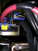
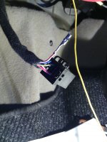
You can test the column before removing the old one. Just disconnect the power supply and data connector (do no disconnect the torque sensor cable) and connect it to the new column. Then using Alfaodb or Multiecuscan check if it is working and if the column is showing around near + - 0º. Also if the Steering column position sensor is present. (DO NOT start engine when testing the new column in this configuration) This can also probably be done with the new ABS ECU.
Once the new Column is in position remove the data connector from the steering column we will now need to rearrange how the can wire are connected.

The old connection is the CAN signals Hi/Lo come from the ABS pump to steering column to connect pins 2 and 3 then leave on pins 7 and 8
The new connection will be CAN signals Hi/Lo come from the ABS pump to Yaw senor then leave yaw sensor to connect to steering column on pins 2 and 3
You can cut the can wire on the plug PIN 2 and 3. Leave about 1.5cm to be able to solder the other wires. (ONLY CUT after confirming the pin location on the plug, it is written on the plug and on elearn. The wire colors for CAN lines were wrong on elearn for my car so CONFRIM pin location) I preferred to remove the pins from the connectors and connect the CAN HI/Lo steering directly on the connectors. If you solder add heat shrink.
CAN Hi Ster. M086 -> K074 (pin 03)
CAN Lo Ster. M086 -> K074 (pin 02)

Next solder the cut CAN wires coming from the ABS to the yaw sensor wires (CAN Hi CAN LO ESP/ABS M050).
Repairs to CAN bus wiring
When repairs are performed, both bus wires must have the same length. When the wires (1) and (2) are twisted, the length of each complete twist must be 20 mm (A).
There must not be any section of untwisted wiring longer than (B) = 50 mm, for example in the vicinity of welded joints.

