

You are using an out of date browser. It may not display this or other websites correctly.
You should upgrade or use an alternative browser.
You should upgrade or use an alternative browser.
Technical X244 cruise control retrofit 2.8JTD 2005-factory parts?
- Thread starter Ocwobio
- Start date
Currently reading:
Technical X244 cruise control retrofit 2.8JTD 2005-factory parts?
OP
OP
- Joined
- Sep 29, 2013
- Messages
- 481
- Points
- 183
Splendid stuff mate. Got a link for the ebay terminal tool please- anything to help make a neat install is welcome! Thanx bud.
OP
OP
- Joined
- Sep 29, 2013
- Messages
- 481
- Points
- 183
Think I found it....18 piece kit from ebay at less than 3 quid. So should be able to cope now, lol. Cheers.
OP
OP
- Joined
- Sep 29, 2013
- Messages
- 481
- Points
- 183
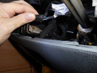
Well, the plot thickens. I have, it seems, the 4 wire brakelight switch. And all 4 terminals seem to have wires to them. There are indeed 4 wires coming from it, I have shown these as they come from the switch to a junction about 6 inches from the switch itself. ( I could not get a pic of the actual switch wire connectors as there was not room to get the connector off, or get the brake switch out; I shall have to remove the lower dash and switch mount if i need to get it out). I also, FWIW, have a clutch switch fitted too. My question, as per Ronnie mc's instructions, is do I need now to bridge pins 3 and 4 on the brake pedal- I can't see any advantage in doing so. Unless I have missed something that would be obvious to a normal human being.....
Bridging pins 3 and 4 would surely negate the n.o. and n.c. functions of the switch?
The brown switch is the clutch one.
Pins 3 and 4 being a n.o. and n.c. pair, bridging them would make them either or both at the same time? As ever, all help is greatly appreciated folks!
Bridging pins 3 and 4 would surely negate the n.o. and n.c. functions of the switch?
The brown switch is the clutch one.
Pins 3 and 4 being a n.o. and n.c. pair, bridging them would make them either or both at the same time? As ever, all help is greatly appreciated folks!
Attachments
Last edited:
OP
OP
- Joined
- Sep 29, 2013
- Messages
- 481
- Points
- 183
Fwiw, has anyone ever seen the x244 steering wheel with the cruise on it? What were the connections like? Presumably, it will have a different slip ring or similar apparatus around the column, I'm feeling nosey, I am using the 147 switch that arrived today.
Communicator
Prominent member
- Joined
- Aug 3, 2019
- Messages
- 3,452
- Points
- 942
Ronniemc,
I have carried out the modifications described in this thread. On initial road test all controls worked, but no indicator light on dash. Using the diode test facility of a multimeter, I could detect a diode in the instrument panel, and in view of remarks read on the Italian forum Camperonline, I did not investigate further. On my next test a few days later, the LED was immediately visible.
I have one serious niggle. I have been unable to insert the male pins into the black Delphi connector. I have even tried new 1.5 Delphi GT pins without success. I cannot get sufficient insertion of the pin to allow gripping it with pliers. My current connections are a combination of heatshrink and cable ties. They make contact, and will not come apart, but are extremely unelegant.
Any hints or tips as to tidying this jury rig would be highly appreciated.
lancepar
Member
When I considered cruise control on our X244 I found this site but that was as far as it went.
https://www.conrad-anderson.co.uk/products/view/cc172030153/wizard:cruise-control

https://www.conrad-anderson.co.uk/products/view/cc172030153/wizard:cruise-control
OP
OP
- Joined
- Sep 29, 2013
- Messages
- 481
- Points
- 183
When I considered cruise control on our X244 I found this site but that was as far as it went.
https://www.conrad-anderson.co.uk/products/view/cc172030153/wizard:cruise-control
:
Hi.. checked them out a few years ago- too dear. I'm looking at coming in well below 50 quid the way I'm doing it. and a good deal of skinned knuckles, aching joints and bad language too. I have all the parts and know where they go, just need time and the urge to dig in and start. I'll post on here when it's done. But when.....?
Communicator
Prominent member
- Joined
- Aug 3, 2019
- Messages
- 3,452
- Points
- 942
Ocwobio,
You have asked several questions on your thread "x244 brake light switch, its a bitch". I think that in the interests of others, my replies are more appropriate to this thread.
1. I confirm that I have recently carried out this modification.
2. I do not have Multicuescan, only a simple code reader, which I have not had to use in a fault situation.
3. I obtained the 12V supply by bridging terminals 1 and 6 (female side) of D160A, and continuing from terminal 6 to the yellow lead of the Affa 147 switch stalk. (Terminal 6 of D160A is supplied from fuse F27.)
4. As previously reported I did not see the indicator light on at first road test, but it came on OK on second test a few days later. In between with battery -ve removed, had separated D001B and checked for the LED (diode test) between pin 2 and the instrument panel (lower) side of F37. Diode present, so left it at that. Subsequent to the second test the LED now comes on for the automatic test period when switching the ignition on. Goes out, and will then illuminate immediately cruise control is switched on, even before the engine is started.
Camperonline forum. I managed the first page with Google Translate, but could not manage to get translations of subsequent pages. Eventually consulted in house expert, our geekish son. Resolved by him in less than a minute, but had to get him to run through the procedure at a slower rate so that my ageing brain could absorb. For the benefit of those who may wish to follow here is the sequence from end of first page.
a) Right click on required page.
b) Left click on "Copy link location".
c) Right click on Google Translate banner.
d) Left click on "Select all".
e) Control V (paste).
d) Enter/Carr Retn
Repeat for subsequent pages, and lookout for errors and Italian idioms.
Bridging wherever.
I canot see bridging at the stoplight switch as being easy, but neither is bridging at D160A, which I found hard to locate using eLearn. It is in fact in the front right corner under the instrument binnacle. Cable form lengths are tight. I pre-assembled a loop of blue wire into a spare AMP 1.5 superseal female crimp for position 1. After removing pin 6 female, I held it with small pliers at the wire crimp while prising open the insulation crimp with a scriber, followed by some straightening with needle nose pliers. The terminal was secured to a small piece of scrap plywood by a cable tie at its front end to secure it while soldering in the loop from pin1. Insulation crimp remade and connector pushed home.
The above is a tricky procedure and others may well be advised to opt for some other form of connection.
For making connections to the Alfa 147 stalk, I used a distinctive blue 6 way 2.8mm blade plug and socket, and for consistency adopted the same pin numbering format as used by eLearn.
Have I missed anything?
OP
OP
- Joined
- Sep 29, 2013
- Messages
- 481
- Points
- 183
Seems pretty comprehensive to me. I am thinking that, as someone on the camperonline pages did, replace the black connector with a completely new item; I have one but it only has 5 connectors and not 6. I will be having a look behind the binnacle anyway, so will look for D160A whilst doing so. I will be able to bridge at the pedal switch if necessary once the switch is out for replacement, by tapping into the wires for pins 3 and 4 rather than trying to attach to the actual connectors in the plug. There is a section of the 4 wires about 6 inches long with connectors both ends that I can take out and solder and heatshrink in a much more amenable postion, then just clip back in when finished. I think replacing the black connector would be the tidiest way to deal with the ECU wires, but as you say, there is very little slack to enable convenience of working. Ebay to the rescue for plugs and sockets, then. I could, in theory, exxtend the wires out from the black plug to get better access.I have some 6 way plugs and sockets but I do not trust their accuracy of register when coupling, so not for this job.
I too have sporadic issues with google translation of pages, last week it worked very well, just translating page 1, then being able to scroll to the next pages in sequence using the page number nav bar above and below. This week I am having to do the first page, go back to the original italian one which remained open, select next page, then translate the new one. It is a browser issue- I use an old browser as it has a super adblocker, and allows me to watch youtube videos at will without any ads butting in. I won't entertain Chrome!
I too have sporadic issues with google translation of pages, last week it worked very well, just translating page 1, then being able to scroll to the next pages in sequence using the page number nav bar above and below. This week I am having to do the first page, go back to the original italian one which remained open, select next page, then translate the new one. It is a browser issue- I use an old browser as it has a super adblocker, and allows me to watch youtube videos at will without any ads butting in. I won't entertain Chrome!
OP
OP
- Joined
- Sep 29, 2013
- Messages
- 481
- Points
- 183
Actually, if I can access the black plug, to extend the wires, assuming I can get the correct sections and colours, I will use molex connectors as I have some around. They are ex-PC and 4 way, so 2 will do it. Plus, i have the corect pin removal tool which works a treat on these!
Communicator
Prominent member
- Joined
- Aug 3, 2019
- Messages
- 3,452
- Points
- 942
Access to connector D018B is much improved if you bite the bullet and remove parcel shelf, plus LHS lower dash and glove box. Lots of screws into clip on "spire" nuts with T25 head, plus one M6 at bottom, with H5 recess head.
The T25 screws are one recessed near quarterlight, one behind oddment tray above fuses. (Flip tray out with wallpaper stripping knife or similar tool.) Four screws along top of glove box (not two holding latch), and two in rear of glove box recess. Then two at front of parcel tray, all much easier than lower two on steering column cover.
For the lower steering column cover I have fitted a 20mm length of reinforced PVC fuel hose over the end of a standard PZ2 driver. This makes screw head location much easier. For replacing check alignment with torch and mirror, before using a claw type retriever as a screw starter.
The area above my LHS fuseboard is a mess, due to the activities of an alarm installer commissioned by the converters. Wiring scrambled, and unmounted connectors in a bundle, but with the lower dash panel removed it is fairly easy to get to the black connector D018B. This connector is a sealed Delphi Hybrid accepting larger inserts in in ways 3 & 4. These two centre ways are used by the cab aircon option, and would need to be high current rated if aircon is fitted. I have considered replacing the female section, which on my vehicle only carries the cruise control wires. In this case I could label it D018C. I have download drawings of the Delphi connector, and may see if I can work out where I am going wrong. Meanwhile my jury rig will hold together.
After taking the parcel shelf out, I removed the radio and message holder assembly. With the binnacle removed I was able to run a fish wire across the front, through the existing cableform supports. Made a tidy job of the cable run. Two metres of cable were sufficient to run between the new Alfa 147 stalk connector and D018B, plus another metre to connect to 12V +ve at D160A/1.
The final work of cutting the slot for the Alfa 147nstalk in the lower steering column cover should not be rushed. The wiring is out of sight, but it would be difficult to hide a badly cut slot. I made a cardboard template, to which I made several adjustments before marking out and cutting the slot.
Communicator
Prominent member
- Joined
- Aug 3, 2019
- Messages
- 3,452
- Points
- 942
I should have added that as regards cable colours, I try to match the base colour, and then add a coloured band at each end as a marker. Normally I use stretched short lengths of coloured PVC sleeving (very old stock), but in this case I bought a lengths of purple and green heatshrink. The large unused quantity has boosted my stock of heatshrink for future jobs.
OP
OP
- Joined
- Sep 29, 2013
- Messages
- 481
- Points
- 183
This info is solid gold to me. I will likely end up biting said bullet. However, I think that some of the panel screws that you refer to as near the quarterlight, will be a problem for me, as it is an A class and thus from the dash panels back, including the side walls, is all bespoke. I have seen in eLearn 2 screws that locate transversly near the position of the door A pillar on a regular cab, that if fitted to mine, are inaccessible. We shall see.
I too had a hantle of bother getting a Torx bit on to the column shroud screws, so your tip is welcome. Same in my Smart car too, strangely, almost an identical layout.
As for wiring mess made by the convertor, most MoHos will have some. Mine has some under the flip up clipboard for the radio.
I have aircon in mine so will need to accomodate the extra cross section of the wires in any new plug. A deep breath and dive in, then, and maybe take pics as I go just in case!
Last edited:
Communicator
Prominent member
- Joined
- Aug 3, 2019
- Messages
- 3,452
- Points
- 942
On reflection, I thought that I had written too much, but as the detailed info is appreciated I will expand on a few items.
The screws at the front lower dash covers of my PVC are symetrical, and close to the A pillar. If I follow a line round the corner below the heating vents, I can find the recessed screw head just as I touch the door seal. If you have problems reaching this screw, right angle torx wrenches, or mini thumb wheel ratchet wrenches come to mind. It is possible to remove the parcel tray (no passenger air bag) without removing the lower dash. Just remove or loosen the screws as appropriate. The two components clip together, so replacing could be tricky.
On my vehicle you would find it difficult to remove the lower steering column cover screws with a Torx bit, as they have PZ2 heads. Incidently the fuseboard cover screws are PH2, why?????
As you have aircon, if you wish to bypass the black Delphi connector why not leave it in place with the aicon connections, and divert only the four cruise control connections?
My radio connections are tucked away, but I am considering mounting a no screen dash cam at the front of the clipboard. (All dash cameras offered seem to be screen cameras, and these would interfere with Remis blinds.)
OP
OP
- Joined
- Sep 29, 2013
- Messages
- 481
- Points
- 183
Hello again!
"As you have aircon, if you wish to bypass the black Delphi connector why not leave it in place with the aicon connections, and divert only the four cruise control connections?"
That is what I intend to do. A single Molex will the suffice, 4 way and will take the current involved. I even though about picking the 4 wires up in the engine bay nearer to the fuse box therein, and going in thru the dash at the RHS, I will have a look to see the possibilities in the next day or two.
As for too much info- not a bit of it! If I can't accomplish this job now in light of the foregoing, well, I deserve to watch Barbie doll unboxing videos on youtube for the rest of my days.
OP
OP
- Joined
- Sep 29, 2013
- Messages
- 481
- Points
- 183
Sorry for late reply! I have the same switches, so this will work. The thing is, we are not changinging the wiper or light switches. I have Alfa one that came with the cruise switch, don't know if they can be swapped over all as a unit, but not necessary anyway. Just add the Alfa cruise lever to our existing switch module- there should be a recess that is made for it.Logic then says that being as the Duc had steering wheel controls for the cruise, this suggests that the whole switch assembly may well work as a complete unit, lights, wipers and all. But check first and I don't take responsibility if it won't, lol.Hi im new to the forum. I have sourced the parts mentioned above but the indicator stalks are different will this still work. I have a 2002 ducato 2.8.
Thanks
Glen
OP
OP
- Joined
- Sep 29, 2013
- Messages
- 481
- Points
- 183
I am now part way thru this job. I have connected to the wires from the ecu in the black plug, by cutting the required 4 wires short of the connector and extending a little into a 4 way ex-pc Molex connector, thence via 7 core trailer cable to the vicinity of the stalk switch location. I had to substitute the orange wire of the stalk for the brown one in the 7core as this does not contain an orange strand. (BTW the pins removed from the stalk switch leads are a very near match to the black connector ones needed, but getting them in was a problem due to 1- space, 2- not sure they would 'click' into the housing, but they fit the slots well).
I now need to fit the stalk, connect the 4 of the wires from that to the 7 core as per colours in that, watching for the fact that brown is the new orange. This then leaves the yellow one to connect. Most users of this stalk cruise switch connect the yellow to pins 1,3, and 4 (IIRC) on the brake light swich. As I have 4 wires going to all pins of a 4 pin brake light switch (not yet fitted, later today hopefully), it looks like I won't have to bridge pins 1 and 3 there, if I have this right, just taking a key switched live feed from a suitable other point. I have one in mind.
So, bottom line--do I have to take the yellow from the stalk to the brake switch, and pick up a feed there? Or as there are already 4 wires into/out of the switch, (2 normally open, for the brake lights, and 2 normally closed for cruise I think?) it is already set up for cruise apart from the + switched supply to yellow , and once that is taken from elsewhere, no further need to attach any connection to the brake light switch is necessary? If you see what I mean. In short, can I forget the yellow to brake switch and bridging pins 1 and 3 there if an alternative supply is used?
I am taking pics as I go and will hopefully be able to do a write up on here when finished. I may have to stop for a while and return to it later, depending on progress rate. I have some other things to do while I have the tools out and dash partially stripped.
Last edited:
OP
OP
- Joined
- Sep 29, 2013
- Messages
- 481
- Points
- 183
Just tried to get the brake switch changed. Totally impossible. I cannot get a mini grinder/dremel in, to make a recess in the metalwork behind that stops removal of even the plug, never mind the switch. As the steering column is in the way,and can't get lower dash panel off anyway as one screw is buried in the sidewall structure. Also got the wrong switch anyway, the operating 'tit' sticks out too far by at least 5mm.
Also unable to bend brake switch bracket down enough to allow removal of switch or connector plug.
It is also not possible to splice into the wires to the switch as I can't do it one handed- cutting, stripping, soldering and heat shrinking.
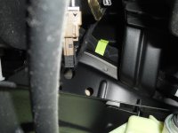
So, it looks like I will have no choice to connect into the (D160A?) connector wherever that is to be found.
Anyone got a pic?
Found a likely suspect but can't i.d. it and need to know where the pins to bridge are in it, and how many wires go in? I got it into my head that it is an unused connector with quite a few wires into it? Think I need pins 1 and 6 jumpered together, them the same wire from that jumper goes off to the cruise stalk yellow wire.
This job is crashed and burning just now, can it get any worse?:bang:
Also unable to bend brake switch bracket down enough to allow removal of switch or connector plug.
It is also not possible to splice into the wires to the switch as I can't do it one handed- cutting, stripping, soldering and heat shrinking.
So, it looks like I will have no choice to connect into the (D160A?) connector wherever that is to be found.
Anyone got a pic?
Found a likely suspect but can't i.d. it and need to know where the pins to bridge are in it, and how many wires go in? I got it into my head that it is an unused connector with quite a few wires into it? Think I need pins 1 and 6 jumpered together, them the same wire from that jumper goes off to the cruise stalk yellow wire.
This job is crashed and burning just now, can it get any worse?:bang:
Last edited:
Communicator
Prominent member
- Joined
- Aug 3, 2019
- Messages
- 3,452
- Points
- 942
Ocwobio,
Where do I start? The connector D160A will only give you the 12V supply from F27. As previously stated D160A is located front right, under the instrument binnacle, and to quote the translation from the Italian, "There is not much wealth of cable." I had to release the plastic holder from the framework to gain access. On the female side of D160A pin 6 is fitted with a single 0.75mm Wh/Bl wire, I managed to solder an 0.5mm blue loop for connecting to pin 1, where a new female terminal is required. A second wire wire from pin1 is required to extend the supply to the yellow wire of the Alfa 147 stalk. I think that it may be possible to use red "Scotchlok" IDC connectors rather than install two wires in a single terminal insert. I used a spare AMP superseal female insert at pin 1. It latched in position OK.
I do not think that removing the RHS lower dash panel is essential, but it allows more light on the scene. Back to filing, or repeat relay, both of which present problems. I have measured the brake pedal switch that I removed from my vehicle. The operating button protrudes about 11mm, but the plot thickens. Illustrations on the Italian Camperonline site show the two pin switch as I have described, but the replacement 4 pin switch appears longer as you have described.
The new switch that I fitted was a LEMARK LBLS090, ordered on Ebay from All Car Parts Ltd. Another number on the box was A036829. Ebay item No. was 2917 0454 2326. I searched for Fiat Part No. 1029 5468 4051 0. Cost was £8.12 delivered.
I have some pictures but they are still on my camera card. For a quick view of some photos follow the following link to the Italian site, and scroll down. https://forum.camperonline.it/tecnica/meccanica/cruise-control-alfa-147-su-ducato-244-aiuto/222555
I hope that the above is of some help.
Last edited:
Similar threads
- Replies
- 17
- Views
- 1K