Technical wiring diagram

Currently reading:
Technical wiring diagram

Remember it is possibly NOT the drawing that correspond to your car, why I've been asking for the connector type ...
 
Hi Paullap,

Almost all gasoline Fiats with 1.4 engine use the CFC328 ECU unit fitted to the C514 gearbox (2 connector that Bernievarian showed).
s-l1600 (1).jpg

s-l1600 (2).jpg

s-l1600.jpg


The 1.3 diesel six speed with CFC300 fitted to the M20 gearbox (1st conector that Bernievarian showed)

Depending on the gearbox a different type of robot is used. Even though the basic concept of how it works is the same on all dualogic units.


The control unit (ECU) on CFC300 is bolted directly onto the robot unit and connect to the solenoids with terminals. To change the solenoids you need to remove the control unit using a puller (a bad design.) (also used on the CITROEN C4 Picasso EGS Gearbox)
s-l1600 (5).jpg

s-l1600 (4).jpg
However in your case the CFC328 is a separate unit connected by wiring loom. To find the ECU to to follow the wiring from the electric motor.

Very really do these ECU fail what can happen is that the ECu commands an action and since nothing happens the ecu think that it is at fault when another factor is preventing the action from being carried out. (However there are always exceptions )
 
I think Tonico meant " Very rarelly do these ECU fails …" ;-)

And BTW, the CFC300 uses the two FIRST connectors I posted, and the CFC328 uses the 2ND one (with lot more pins). As the pin out of the last correspond to the drawing I sent I Believe it is the correct one …


BRs, Bernie

If someone here helped You fix -or better, understand- your issue, hit the thanks icon @ bottom right corner, it's free and makes us feel helpy ;-)
 
Last edited:
Hi I still cant find this gearbox ecu, All the wires from all the sensors go to a big connection plug and then the wires go in to the main loom where I am sure it goes inside the car behind the glove box.

The unit behind the glove box is part number 00518263170 I am sure the is the body/ comfort control module.


I am lost

Paul
 
Doing some searching om the net, it sounds like the gearbox ecu could be under the carpet on the passenger foot well. Ill have a look tomorrow.


Paul
 
Hi , Sorry I have been away, This is where I am so far. I purchased multiecuscan diagnostic software and all loaded on the lap top and this is what I found.


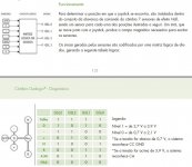
Fault code P060C-85 control unit faulty ( microprocessor) same as before

Error details
Operating time 4256 min
Engine speed 1204 rpm
hydraulic circuit pressure 44 bar
gearbox oil temp 21 Deg C
Gear engaged N
Battery voltage 12.9v


Then No help available
The fault is present now, Take appropriate action to fix this sensor fault.
Dashboard light was activated for this fault

I then did the part to activate the pump and solenoids ect.

All worked ok until I git to the relay part
it came up with a failed to Execute, Incorrect conditions to run this test.

Not sure where to go now.

Paul
 
Hi Paul, have you checked the GB lever output table and the brake switch status ?? You said error P1772 in the OP, is that gone now ??

BRs, Bernie

If someone here helped You fix -or better, understand- your issue, hit the thanks icon @ bottom right corner, it's free and makes us feel helpy ;-)
 
Hi Bernie, I have checked the brake switch status, Not sure what you mean by the Gear box lever table, The diagnostics can see N and auto but nothing else. the same on the dash.


What is playing on my mind is the "relay" The multiECUscan when in the gearbox and you can activate the solenoids pump ect , it all works apart from the relay, It does not just click like it should, it like flutters and then I get the message

FAILED TO EXECUTE
incorrect conditions to run thus test


I am thinking of of getting hold of a working unit complete and swapping it over, just to see if it is a wiring or actuator problem, I am not sure they are interchangeable without coding.


Regards

Paul
 
What robot version is reported by MES ?
Is error P1772 gone ?

See attached the "table" I was talking about …

BRs, Bernie

If someone here helped You fix -or better, understand- your issue, hit the thanks icon @ bottom right corner, it's free and makes us feel helpy ;-)
 

Attachments

  • Dualogic gearlever logic.JPG
    Dualogic gearlever logic.JPG
    79.2 KB · Views: 306
Hi Bernie, I am not sure where to find that table as I have only had the software a few days, The P1772 has gone, all I have is P060C-85 Control unit faulty ( microprocessor ).

ecu iso code BC 07 98 08 38
fiat drawing number 51857903
hardware number cfc 328F.06
hardware version 00
software number FHA20DAO
software version0000
Homologation number blank
Functioning time eprom 4198 mins
operating time 4221 mins


How do you know so much about these gearboxes, Do you work for Fiat.
I am just a car nut, I love solving these sort of problems out.


Regards

Paul
 
Hi Paul,

you have to build the table yourself by taking voltage measurements on the 4 output lines of the gearbox lever; if you find a discrepancy between what you got and what should be, you'll get the reason why the system doesn't work as it should ...

There are a lots of interesting manuals laying on the net, it takes time but you'd finally have all you need to "know so much" , this + 40 years experience in technical industry helps a lot helping others …
BTW, your GB robot is CFC328 (from the MES file you sent)

BRs, Bernie

If someone here helped You fix -or better, understand- your issue, hit the thanks icon @ bottom right corner, it's free and makes us feel helpy ;-)
 
Good evening Bernie, Thanks for the info. I am a mechanical engineer 61 years old and still working, I spend a lot of time trying to fix cars that friends give up on. I dont charge any money, I just get a great feeling when I finally get to the bottom of a problem, I just love learning. and It is mostly down to people like yourself that give up the time to help others. so a very big thank you for taking the time to help me. But I need a bit more guidance as to how to do these test on this car please if you have the time.

I am not very fast at finishing anything, I have just rebuilding a Lea Francis 2 1/2 liter sports ( it took 20 years) but I have finished it, I did everything from a bare chassis up apart from the leather interior, I will never give up anything.

Kind Regards


Paul
 
Hi Paul,

You'll have to gain access to the GB lever connector first. Once there find the pin #6 that feeds the unit with 12VDC, this step to determine the other pins location…

Here is the pin assignement;

1: Wheel paddles (optional)
2: GSL 0
4: GSL 1
5: GSL 2
3: GSL 3
6: Power in (+)

At that point You'll have to power the unit (ignition ON, engine stopped) and place the lever in every position in order to measure the voltage that should be present, High or Low, on the various channels with respect to the logic table.

If ALL measurements are ok, You can rule-out the GB lever. BTW this lever is built around 7 Hall-effect sensors, a magnet and a diode array; parts that can fail (but the magnet ?) so its a potential candidate for Dualogic malfunction...

I've attached the nodes interconnection so You can see what sensors are involved, it's in Portugese but hey Google Translate is there !

BRs, Bernie

If someone here helped You fix -or better, understand- your issue, hit the thanks icon @ bottom right corner, it's free and makes us feel helpy ;-)
 

Attachments

  • Dualogic nodes connect.JPG
    Dualogic nodes connect.JPG
    67.9 KB · Views: 313
Hi Bernie, I haven't given up on this car, I have been busy on another car, This gear lever switch do I need to remove the center console to get at it. I am going to try to get to it today.


Thanks


Paul
 
Hi Paul,

according to other threads it is accessible from the console …

Regards, Bernie
 
Back
Top