OP
OP
I've been doing a bit of digging with this problem..... Here's my theory....
I have discovered that cars these days have up to three bus systems, One High Speed CAN bus, One Low Speed CAN bus, and a LIN bus.
The High Speed CAN bus (1Mb/s+) is pretty much dedicated to the engine, which sounds logical considering all the hight speed decisions to be made and responded to.
The Low Speed CAN bus (40-125 kb/s) is for (IMO), things like ride handling, airbags (if 8x10⁻⁶s is fast enough), ABS, etc, i.e. the next level of importance/speed requirements.
I explored LIN bus because that was stamped on the alternator & the circuit diagram, and apparently is a single wire (but uses vehicle ground to complete a circuit) capable of between 1-20kb/s, and used typically for boot/doors/stuff open/closed, typically stuff that you wouldn't notice if it took an extra half second or so, to change switch a light on/off.
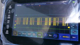
Now I believe that the alternator has a processor onboard the voltage regulator assembly, that expects a handshake signal on the LIN bus sent from the ECU, I guess to acknowledge communication maybe, and is then followed by regular bursts of approx ten pulses whose duty cycle represents the amount of current the alternator needs to output.
According to YT videos, I should be able to connect an oscilloscope to the LIN bus wire as the alternator, which will tell me:
A. There is no signal from the ECU.
B. There is a short circuit between the ECU and the Alternator.
C. The new Alternator is also faulty.
D. I'm barking up the wrong tree.
Can't connect an oscilloscope, because about a year ago, when I was having a tidy up, it was taking up valueable space on my workbech so I gave it to a friend, and anyway it was to big and cumbersome to be portable, and was one of the old CRT types with no storage. New one turns up after Xmas.....
Still charging every day at the mo'
I have discovered that cars these days have up to three bus systems, One High Speed CAN bus, One Low Speed CAN bus, and a LIN bus.
The High Speed CAN bus (1Mb/s+) is pretty much dedicated to the engine, which sounds logical considering all the hight speed decisions to be made and responded to.
The Low Speed CAN bus (40-125 kb/s) is for (IMO), things like ride handling, airbags (if 8x10⁻⁶s is fast enough), ABS, etc, i.e. the next level of importance/speed requirements.
I explored LIN bus because that was stamped on the alternator & the circuit diagram, and apparently is a single wire (but uses vehicle ground to complete a circuit) capable of between 1-20kb/s, and used typically for boot/doors/stuff open/closed, typically stuff that you wouldn't notice if it took an extra half second or so, to change switch a light on/off.
Now I believe that the alternator has a processor onboard the voltage regulator assembly, that expects a handshake signal on the LIN bus sent from the ECU, I guess to acknowledge communication maybe, and is then followed by regular bursts of approx ten pulses whose duty cycle represents the amount of current the alternator needs to output.
According to YT videos, I should be able to connect an oscilloscope to the LIN bus wire as the alternator, which will tell me:
A. There is no signal from the ECU.
B. There is a short circuit between the ECU and the Alternator.
C. The new Alternator is also faulty.
D. I'm barking up the wrong tree.
Can't connect an oscilloscope, because about a year ago, when I was having a tidy up, it was taking up valueable space on my workbech so I gave it to a friend, and anyway it was to big and cumbersome to be portable, and was one of the old CRT types with no storage. New one turns up after Xmas.....
Still charging every day at the mo'


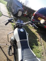
 nice on longer trips as you can shuffle your feet around and change position to get comfy
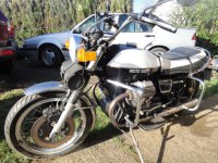
 . I stuck the front crash bars on it last summer, and plan for some additional running lights to go on them. When this wind dies down I'm gonna get out there under my canvas and have a play.