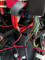
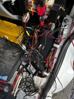
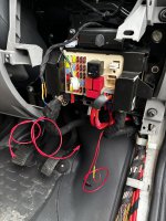
Look at this bad boy - I’ve been working through the gnarly bits of our IH PVC and have moved to this terrible tangled web - whilst removing the defunct Laserline alarm with central locking interface, I uncovered main harness wires cut and bridges made with soldered resistors - I’m assuming this was to prevent canbus errors??
It looks like the Soldering Seagul has been flying past ….
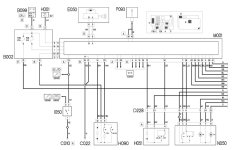
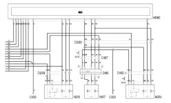
I could do with a wiring diagram so I can double check what I am rejoining - please can some point me in the direction of one ? - harness to dash fuse box, Ducato X250 2008

It looks like the Soldering Seagul has been flying past ….
I could do with a wiring diagram so I can double check what I am rejoining - please can some point me in the direction of one ? - harness to dash fuse box, Ducato X250 2008
- Model
- Ducato 2008 3.0d X250
- Year
- 2008
- Mileage
- 48000
")