Technical split relay on 2003 Swift Sundance

Currently reading:
Technical split relay on 2003 Swift Sundance

Joined
Apr 26, 2025
Messages
11
Points
55
Location
sunny belfeirste
Heya, I'm trying to fix a fault with the split relay as there's no increase in the leisure battery voltage with the engine running. Is this the split relay and are these the fuses.
Also are there any manuals for the 2003 Ducato 1997cc van...thnx👍
 

Attachments

  • Screenshot_20250427_081803_Gallery.jpg
    Screenshot_20250427_081803_Gallery.jpg
    1.1 MB · Views: 28
  • Screenshot_20250427_081733_Gallery.jpg
    Screenshot_20250427_081733_Gallery.jpg
    1.1 MB · Views: 19
The correct title is "split charge relay", In reality, as perhaps you are aware it is nothing magical. It connects the habitation and starter batteries in parallel when the engine is running.
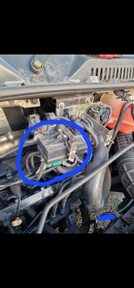
The relay unit indicated seems more akin to a glowplug relay.
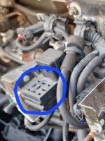
The fuses shown (2 x 20A & a 15A are probably for the two batterries, and the fridge (15A). I would expect the two 20A fuses to be for the two batterries and if so shoulld be connected to terminals 30, and 87 of the split charge relay.
Your photo shows two adjacent relay sockets, with one being empty. Concentrate your efforts in this area, as I would expect to see a fridge relay adjacent to a split charge relay on this type of installation.
The relay coils (terminals 86 & 85) may be connected in parallel, and one side 85? should be to chassis. The other terminal (86?) should be connected to D+. An alternative is to power the split charge relay via the fridge relay contacts. This reduces the load on the sensitive D+, alternator field circuit.
The fridge 15A fuse should ideally connect between the starter battery and the fridge relay contact 30, with 87 on the same relay going to the fridge 12V element.
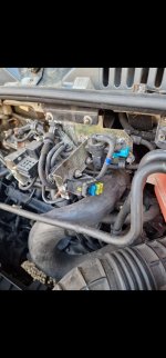
May I suggest some wire tracing around those three fuses. Disconnect both battery negatives before doing any work, as both sides of the split charge relay are normally live at 12V, You seem to be missing a relay.

All of the relays should be covered by a plasic hood, which is normally secured to the two M6 forward facing studs.

Given the year 2003, your vehicle is most probably an x244 model (2002 - 2006). Confirm with first three numbers of VIN e.g. ZFA244..........
eLearn for the x244 runs on a Windows computer, and can be purchased as a CD for about £5, or downloaded from the forun "Downloads" section, for which see black ribbon at top of page.

Edit.

I note that the vehicle is a Swift conversion. Swift typically use Sargent manufactured electrical systems for the habitation system. Sargent are consistent with their wire colour coding.

Brown/Green = Starter Battery

Brown/Blue = Habitation (Leisure) Battery

Red/Yellow = Fridge

White/Orange = Earth

Blue = Vehicle D+
 
Last edited:
Your photo shows two adjacent relay sockets, with one being empty. Concentrate your efforts in this area, as I would expect to see a fridge relay adjacent to a split charge relay on this type of installation.
...You seem to be missing a relay.
so it's likely that the split charge relay should go here...
Would it be the same relay as the 12V fridge relay?...thnx👍
 

Attachments

  • 20250426_200653.jpg
    20250426_200653.jpg
    590.6 KB · Views: 10
There is a high possibility that the vacant position is for a split charge relay, but this is not proven.

It is also not certain that the relay adjacent to the empty socket is the fridge relay.

Further wire tracing/colour checking of the connections to the relay sockets iwould confirm the intended use of the relays.
An alternative for the fridge relay would be to test for 12V to the fridge element with engine running. 12V should be present only with the relay in place.

As the circuits are only fused at 20A, a relay of the same specification as the fridge relay would suffice, but I suggest a 40A rating, as a minimal decrease in contact resistance can improve habitation battery charging.

The present situation begs the question as to why the split charge relay appears to be missing. It could have been replaced by a larger relay elsewhere, or has a previous owner installed a B2B charger, which has subsequently been removed, or failed?

As your knowledge of relays appears to be minimal, be warned that there is a lot of energy stored in the batteries. If you inadvertantly create a short circuit, a vehicle fire could be started.

There is also the possibility that if the relays have been left exposed without the protective hood, corrosion of the connections may be a problem. I have read of faults on similar installation being traced to corroded connections.
 
Thanks for the further info & tips. There is 12V supply to the fridge whether or not the engine is running- it's connected to the leisure battery for some reason. Still no further on with tracing the split relay wiring so far😐
A 3 way, or automatic energy selection (AES) fridge requires two 12V supplies. These are a lower current supply for the electronics, which must be available whenever the fridge is in use, and is normally taken from the habitation battery. The second supply is for a higher current and frequently fused at 15A. In most cases this supply is only available when the engine is running, as it is typically controlled by the fridge relay, which is energised by D+. The actual connection could be via the habitation battery, but if the split charge circuit is faulty this arrangement can allow the fridge to discharge your habitation battery while you are driving. It has happened.

The colour code used by Sargent for the permanent 12V supply to the fridge is Brown/Yellow. As previously stated Sargent use Red/Yellow for the fridge 12V element supply, which is controlled by the fridge relay.

Perhaps the attached extract taken from a Sargent diagram will expediate you wire tracing.
 

Attachments

  • Sargent Fridge & Step.pdf
    93.9 KB · Views: 8
Back
Top