How much did you skim it so you had to mess with the pistons? According to my calculations 06 to 07mm will take me close 09:1 but I will know for sure when I do the volume measurent. I hope that valves will be clear of pistons after that.


You are using an out of date browser. It may not display this or other websites correctly.
You should upgrade or use an alternative browser.
You should upgrade or use an alternative browser.
Tuning Looking to go faster
- Thread starter gordinir8
- Start date
Currently reading:
Tuning Looking to go faster
Hi Thomas, I'm afraid I don't know how much material was removed from my heads as it had been done before I obtained them.
However, I can say that my first head has a capacity of only 34.2cc and it was difficult to obtain the required 1mm squish band by fitting a 0.5mm copper gasket and a lower support plate, that is why we took some material from the pistons to get the figures correct and a C/R of 10.5:1.
My other head has a capacity of 35.7cc and using a 0.5mm copper gasket and a base plate we managed to get the 1mm squish band and C/R of 9.5:1 I have never had a problem with valve to piston clearance. Hope this helps.
Ian.
the hobbler
Distinguished member
- Joined
- Jul 25, 2012
- Messages
- 4,495
- Points
- 1,129
Morning Thomas:-- If the head has not been skimmed before, I have found that 1.0mm (40thou) is quite safe to remove. On the engine that i have in my car at the moment (659cc---652 + 0.4mm) I have taken 40th off the head, used a copper 0.5mm head-gasket and the thin copper seal rings between the barrels and the crankcase. So far, no problems.Matching the exhaust elbows, this is the outlet and there is some material that can be cleared off.
View attachment 401609
Have you measured the compression ratio? Close to 1:10 I guess. I have also cooper cylinder bottom seals and 06mm cooper gasket. But not quiet sure if head has ever been skimmed so I better measure it first.Morning Thomas:-- If the head has not been skimmed before, I have found that 1.0mm (40thou) is quite safe to remove. On the engine that i have in my car at the moment (659cc---652 + 0.4mm) I have taken 40th off the head, used a copper 0.5mm head-gasket and the thin copper seal rings between the barrels and the crankcase. So far, no problems.
Hi Thomas, for maximum reliability I would stay within 30 bhp (ps) as with the Panda 30 the last of these engines, and complete any work (calculations) that you need the achieve this.
Ian.
Ian.
It used to be normal practice to remove material to blend the exhaust port in the cyl. head to match the exhaust manifold and also where the manifold joins the exhaust pipes i.e. to have a smooth transition.Matching the exhaust elbows, this is the outlet and there is some material that can be cleared off.
View attachment 401609
Research has shown that it's better to have a step where the exhaust pipe meets the manifold - or where the exhaust pipes meets the exhaust ports, if using separate 'headers' (i.e no cast iron manifold). This step should be a sharp increase in cross-sectional area as the exhaust gas is pushed out i.e. pipe larger than port and should have a sharp not a rounded corner. This step or increase in cross-sectional area doesn't reduce engine power but the step helps prevent back-flow of exhaust gases which, by slightly polluting the incoming fuel/air charge, can reduce power. This step only needs to be about 2mm.
In the case of the classic 500, I think I'd match the exhaust ports in the head to the exhaust elbows but leave any step up between exhaust pipes and exhaust elbows as it is. Looking at the above picture of your existing exhaust elbows, it looks like you already have a sharp step and that your exhaust pipes are possibly? slightly larger than the exhaust elbow bore, (given the pattern of carbon build-up). Maybe Fiat Engineers knew something and were ahead of normal thinking at that time?
Re:- piston to valve clearance? I don't think you'll have any problem, given the valves are recessed in the cyl. head because of the combustion chamber shape and your pistons have flat crowns/tops. Have you tried fitting the valves without springs etc. and opening them by the amount of normal valve lift to see if they actually protrude beyond the head gasket surface?
Re:- Maximum compression ratio for everyday, reliable use not maximum power? I'd agree with staying with 9 or at most 9.5:1., given modern fuels typically having lower Octane numbers plus other issues. Also, the fact that you're using the car in a hot climate, probably safer to remain conservative on compression ratio?
Re:- Mirror polishing of combustion chambers, ports etc.? (does anyone mirror polish piston crowns??, (although some modern pistons come with a coating to afaik prevent heat transfer?). I don't think this is necessary on a road-going engine, but bear in mind that mirror polishing may adversely affect smoothness of idle by reducing turbulence causing fuel drop-out from the mixture charge being drawn in. I like a smooth idle on a road car...
Re:- Fitting valve stem oil seals. I'd certainly fit them to the inlet valves but not to the exhaust valves for the reasons stated by others - once you have correct valve stem to guide clearance there shouldn't be any problem with excessive oil getting down the exhaust valve guides.
The exhaust valves have a very hard life, especially on air-cooled engines - they only get some cooling effect through the valve seat when closed and a little through the guide otherwise. I'm sure they'd appreciate a little oil. Remember also, the exhaust valve to guide clearance space is not usually under any vacuum/depression, so oil isn't going to be sucked past, it can only trickle down under gravity. Whereas the inlet valve to guide clearance space is under vacuum during every intake stroke - this is why you get a puff of blue smoke (oil being burnt) when you open the throttle after being on the over-run for a while, indicating oil getting into the inlet tract usually due to excessive valve stem to guide clearances or worn valve stem oil seals.
But inlet valve stems could probably also benefit from a little oil, I've sometimes wondered if the valve stem oil seals shouldn't be fitted at the bottom of the valve guides instead of at the top (I'm not aware of any engine that has them at the bottom of the valve guide)- this way the valve stem & guide would get oil but the oil would be prevented from being drawn into the inlet tract.
I would agree with blending/smoothing of the inlet tract but wouldn't 'knock myself out' doing it. Biggest hurdles are the restricted size/shape of the Siamese inlet tract and the protrusion of the valve guides into the inlet ports - you could always reduce this protrusion by leaving more of the valve guides above the cyl. head when fitting them - subject to still having sufficient clearance between valve guide and valve collar etc. and perhaps taper/remove the remaining protrusion (inlet valve guides only).
Additional idea for improving power - Reduce weight of car, stop adding extra stuff onto the car. How much weight are you currently carrying in the car boot?? As Colin Chapman used to say (iirc):- "Add Lightness".
Have you heard of 'Rimflow' valves? Look it up!. It might be possible to modify your valves to a similar pattern, essentially afaik by machining a small depression just inboard of the valve seating surface. This combined with a 3 angle cut on your valve seats might a good approach on your engine.
Hth.
Last edited:
- Joined
- Sep 27, 2020
- Messages
- 412
- Points
- 173
All good points there from @124BC1
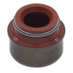
I did a bunch of research into valve stem seals when I rebuilt my Daimler engine recently (so admittedly not an air cooled Fiat engine, but an engine from a similar era), I found that it was suggested that the modern style of valve stem seal, see attached picture for example, does let some oil past by design. I had to use modified valve guides with groves cut to locate this type of seal, apologies I'm still fairly new to the little Fiat engine and I'm not sure if you'd need the valve guides modified or not.
It lets just a tiny amount past that should be enough to lubricate the valve stem without causing any blue smoke or oil consumption. Similarly to how oil control rings on the pistons leave just enough oil on the cylinder walls to avoid excessive ring wear.
With that in mind I'd definitely want them on the intake valves and my default would be to fit them to the exhaust valves too. My only hesitation for the exhaust valves would be, as mentioned above, the nature of air cooled engines which I have little experience with.
Attachments
the hobbler
Distinguished member
- Joined
- Jul 25, 2012
- Messages
- 4,495
- Points
- 1,129
Very interesting observations. The 'step' in the exhaust 'elbow' is there purely because the standard Fiat 500 exhaust has a small'male' lip which fits into the 'elbow' to assist with alignment. I agree that on a highly tuned car that 'lips'on both the exhaust and the inlet tracts are sensible to have to prevent 'reversion' (i.e. gases blowing back). However, being that the average 500/126 engine hardly ever goes above 6000rpm (Cranks tend to 'throw a huff' if you do!) I think that there will be no problem with matching both the inlet and exhaust tracts with their manifolds.It used to be normal practice to remove material to blend the exhaust port in the cyl. head to match the exhaust manifold and also where the manifold joins the exhaust pipes i.e. to have a smooth transition.
Research has shown that it's better to have a step where the exhaust pipe meets the manifold - or where the exhaust pipes meets the exhaust ports, if using separate 'headers' (i.e no cast iron manifold). This step should be a sharp increase in cross-sectional area as the exhaust gas is pushed out i.e. pipe larger than port and should have a sharp not a rounded corner. This step or increase in cross-sectional area doesn't reduce engine power but the step helps prevent back-flow of exhaust gases which, by slightly polluting the incoming fuel/air charge, can reduce power. This step only needs to be about 2mm.
In the case of the classic 500, I think I'd match the exhaust ports in the head to the exhaust elbows but leave any step up between exhaust pipes and exhaust elbows as it is. Looking at the above picture of your existing exhaust elbows, it looks like you already have a sharp step and that your exhaust pipes are possibly? slightly larger than the exhaust elbow bore, (given the pattern of carbon build-up). Maybe Fiat Engineers knew something and were ahead of normal thinking at that time?
Re:- piston to valve clearance? I don't think you'll have any problem, given the valves are recessed in the cyl. head because of the combustion chamber shape and your pistons have flat crowns/tops. Have you tried fitting the valves without springs etc. and opening them by the amount of normal valve lift to see if they actually protrude beyond the head gasket surface?
Re:- Maximum compression ratio for everyday, reliable use not maximum power? I'd agree with staying with 9 or at most 9.5:1., given modern fuels typically having lower Octane numbers plus other issues. Also, the fact that you're using the car in a hot climate, probably safer to remain conservative on compression ratio?
Re:- Mirror polishing of combustion chambers, ports etc.? (does anyone mirror polish piston crowns??, (although some modern pistons come with a coating to afaik prevent heat transfer?). I don't think this is necessary on a road-going engine, but bear in mind that mirror polishing may adversely affect smoothness of idle by reducing turbulence causing fuel drop-out from the mixture charge being drawn in. I like a smooth idle on a road car...
Re:- Fitting valve stem oil seals. I'd certainly fit them to the inlet valves but not to the exhaust valves for the reasons stated by others - once you have correct valve stem to guide clearance there shouldn't be any problem with excessive oil getting down the exhaust valve guides.
The exhaust valves have a very hard life, especially on air-cooled engines - they only get some cooling effect through the valve seat when closed and a little through the guide otherwise. I'm sure they'd appreciate a little oil. Remember also, the exhaust valve to guide clearance space is not usually under any vacuum/depression, so oil isn't going to be sucked past, it can only trickle down under gravity. Whereas the inlet valve to guide clearance space is under vacuum during every intake stroke - this is why you get a puff of blue smoke (oil being burnt) when you open the throttle after being on the over-run for a while, indicating oil getting into the inlet tract usually due to excessive valve stem to guide clearances or worn valve stem oil seals.
But inlet valve stems could probably also benefit from a little oil, I've sometimes wondered if the valve stem oil seals shouldn't be fitted at the bottom of the valve guides instead of at the top (I'm not aware of any engine that has them at the bottom of the valve guide)- this way the valve stem & guide would get oil but the oil would be prevented from being drawn into the inlet tract.
I would agree with blending/smoothing of the inlet tract but wouldn't 'knock myself out' doing it. Biggest hurdles are the restricted size/shape of the Siamese inlet tract and the protrusion of the valve guides into the inlet ports - you could always reduce this protrusion by leaving more of the valve guides above the cyl. head when fitting them - subject to still having sufficient clearance between valve guide and valve collar etc. and perhaps taper/remove the remaining protrusion (inlet valve guides only).
Additional idea for improving power - Reduce weight of car, stop adding extra stuff onto the car. How much weight are you currently carrying in the car boot?? As Colin Chapman used to say (iirc):- "Add Lightness".
Have you heard of 'Rimflow' valves? Look it up!. It might be possible to modify your valves to a similar pattern, essentially afaik by machining a small depression just inboard of the valve seating surface. This combined with a 3 angle cut on your valve seats might a good approach on your engine.
Hth.
You are correct---inlet tracts should only be 'smooth'---it is the exhaust tracts and manifolds that need to be polished. On my 126 (tuned) engine I have smoothed the exhaust guides to match the exhaust tract wall and just smoothed off the inlet valve guides, which protrude more into the air-flow
on the 126 than they do on the 500 heads. On both the 500 and 126 heads there is a quite distinct 'ridge in the tract, just behind the valve---this needs to be rounded off. The inlet port can be opened up to match the gasket of the inlet manilfold. Most of the Fiat 500/126 engines only have'ring' valve seals fitted, which will find there own position on the valve---I think that it was only the later 126s(and Panda30) heads that had 'proper' valve-guide seals fitted, and often only on the inlet valves.
High(ish) octane fuel can still be found----I use the Esso Super 99 Octane fuel, which I am also advised by their web-site, is ethanol-free over the bulk of the UK, despite the fact that the pumps will show "E5"---but I still put in a bit of 'anti-ethanol juice' every time I fill up. For 'road-only' use, I agree in that a compression ratio of 9.5:1 is about optimum. Finally I agree with you---Chapman was right---"add lightness"
I can't disagree with what you gentleman say since all opinions sound logical to me. Now if the step in the elbows is better or worse i am not sure and besides theory needs a lot of practice and experience from a professional tuner to conclude if this 2mm step for this specific low rev engine is better or worse. I took the most obvious way which is: Anything related with fuel and gas passage must be smooth, and polished. I have seen a few racing motorboat engines from the inside and everything was knife edge sharp and mirror polished. Regarding the polishing of exhaust it is good but only for racing use since after a few kilometers it will be rough again from exhaust residuals.
So the moment of truth, primed the carb and almost instant it came to life, those critical first seconds until the oil press light goes out of view always looks longer than they are. Engine looks to operate better than before and i think that it has more power at lower revs. I am not sure what exactly are the benefits of the 35/75 cam vs standard but i noticed a considerable increased torque on my garage ramp (which is underground) Little car tend to accelerate while on top of ramp which usually decelerate. First 1000 kilometers are going to be very hard for me. I am arranging for a Panda carburetor to arrive from Italy and thinking for a Nanoplex ignition system. So with your help here as always another task completed. Now going to measure the compression and see if any differences from theory to practice.
the hobbler
Distinguished member
- Joined
- Jul 25, 2012
- Messages
- 4,495
- Points
- 1,129
So the moment of truth, primed the carb and almost instant it came to life, those critical first seconds until the oil press light goes out of view always looks longer than they are. Engine looks to operate better than before and i think that it has more power at lower revs. I am not sure what exactly are the benefits of the 35/75 cam vs standard but i noticed a considerable increased torque on my garage ramp (which is underground) Little car tend to accelerate while on top of ramp which usually decelerate. First 1000 kilometers are going to be very hard for me. I am arranging for a Panda carburetor to arrive from Italy and thinking for a Nanoplex ignition system. So with your help here as always another task completed. Now going to measure the compression and see if any differences from theory to practice.
So THAT'S what you look like Thomas! Engine sounds good, and yes, the 'running-in' mileage IS a pain, but I am sure that it will be worthwhile.
Ha! Yes this is me. Well 140 psi cylinder press so far measured at cold engine and oil leak from crank pulley...and I said seal is good but better change it with new!! Done 40 kilometres so far and I am happy with it so far.So THAT'S what you look like Thomas! Engine sounds good, and yes, the 'running-in' mileage IS a pain, but I am sure that it will be worthwhile.
Well done Thomas, what C/R did you end up with?
Ian.
Ian.
I don't remember how to calculate compression ratio if I know the pressure which is 140psi but I will check it later. I was expecting about 8.6-9:1 according to my calculations.Well done Thomas, what C/R did you end up with?
Ian.
There is a way, i dont have it off the top of my head.. However, one thing to consider, i dont remember then angle/lift profile for the 35/75 cam, but there have been some cam grinds that offer a pretty aggressive overlap which will show a lower compression when cranking, however will provide a much higher dynamic compression once the engine is running and air is flowing.
Ive installed a kinda goofy cam into my engine, a custom grind 40/80. Its pretty aggressive, and it doesn't show full compression at standard starter rpm.
heres a interesting read imo https://www.badasscars.com/index.cf...duct_id=68/category_id=58/mode=prod/prd68.htm
Ive installed a kinda goofy cam into my engine, a custom grind 40/80. Its pretty aggressive, and it doesn't show full compression at standard starter rpm.
heres a interesting read imo https://www.badasscars.com/index.cf...duct_id=68/category_id=58/mode=prod/prd68.htm
Hi BB, the article is very interesting and I agree with the reasoning behind cam overlap, my present engine has a 40/80-80/40 cam and runs like a dog below 1000 rpm, but with very light internals and flywheel it certainly zings when the rpm gets up. I would still be very concerned about the valve rocker angles and total lift (at the valve) if I fitted a wilder cam, there comes a time when over doing the cam can harm the engine set up  .
.
Ian.
.Ian.
Interesting article Indeed, never had thought of that, now in my case and so far I think that 35/75 cam is a very good choice for neighborhood making noise use and that 8.6:1 ratio looks ok so far. I will have a better view when I will be able to open the engine. Diangelo motori told me that this can produce 40hp at a 650 engine!
Yes if you plan to take the head off, its best to do a CC measurement to get a true C/R.. when i machined my heads i used a "burette" and a peice of clear acrylic plastic to measure the head chamber ML displacement. you can then measure the cyl bore, head gasket thickness and calculate the TDC volume. And by knowing the crank stroke, you can calculate a accurate C/R.
I don't have my notes in front of me, but if i recall, after shaving the head on mine, i settled around 9.4:1 CR. Any more, and things can get a bit spicy on pump gas.
When i rebuilt a 75 2.7 911 engine, its head geomerty and pistion shape did not like anything above 9.5:1 CR on our 91 octane gas. I had to add thicker base cyl shims to bring it down to around 9.3:1.. Just the way this particular engine was.