Not sure if i am allowed to do this. Can a moderator please let me know and delete if nessecary. Here is an extract from the computerised Workshop manual for the GP. Maybe a bit confusing as the pictures are missing:
INSTRUMENT PANEL
Indicators
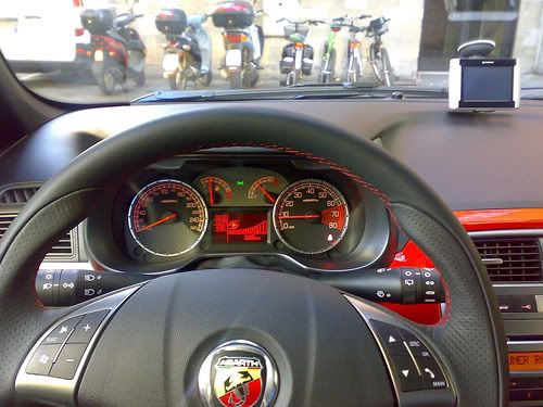
The control panel is installed behind the steering wheel. It is connected to the CAN network and includes 4 gauges built using step motors.
1 - Electronic speedometer
2 - Fuel level (with insufficient fuel level warning light)
3 - Engine coolant temperature gauge (with overheating warning light)
4 - Electronic rev counter
5 - Display (available in three different versions)
Warning lights
There are also numerous LED negative contrast warning lights (there is also preparation for warning lights that can be activated by the CAN).
Buzzer
The instrument panel contains a buzzer with 8 different settings to carry out the following functions:
- alarm/warning/danger signals
- parking sensor signals (where fitted)
- robotized gearbox signals (where present)
- Sealt Belt Reminder
- direction indicators / hazard warning lights activation
- button pressing roger beep
The acoustic signals can vary in intensity and frequency depending on the function signalled.
The volume for the alarm signals can be adjusted down to zero (signal excluded) except for the seat belt reminder and direction indicator/hazard warning light signals which is fixed and the parking sensor which has a minimum volume that is not zero.
Keys
The instrument is connected with 5 external keys on the left side of the dashboard for the management of the headlamp alignment corrector (buttons CAF+, CAF-), the dimming and the setup menu ("MENU ESC", "+", "-" buttons).
1 - "MENU ESC" button:
2,3 - "+" and "-" buttons:
4,5 - "CAF+" and "CAF-" buttons:
"MENU ESC" button:
- pressing it briefly allows the activation of the set up (illustrated below) and confirms it and memorizes the settings
- pressing it for longer produces the return to the standard screen
"+" and "-" buttons:
- allows the selection, setting and adjustment of the functions in the set up menu
- allows the adjustment of the dimming when not in the set up menu
"CAF+" and "CAF-" buttons:
- adjust the setting of the headlamp alignment corrector
The TRIP function is managed by the sepcial button in the steering column switch unit
Display
The control panel display is available in three versions depending on the vehicle''s on-board features:
- COMFORT type display
- MODAL type display
- MATRIX type display
Displays at the Key OFF
With the front doors closed at the key off, the display is not lit up.
The display comes on for 10 seconds and shows the clock and the total milometer at the Key OFF when at least one front door is opened/closed.
Comfort type display Example: standard page at Key ON with dipped headlamps on.
It is a positive transreflective three-line alphanumerical FSTN type display.
The top line, with 14 dot matrix characters (7x5) is for displaying:
- Date
- Trip computer data (processed by the control panel)
- Set-up menu with messages for settings/adjustments
- Messages about: activation of functions/service/faults/information/feedback
- Repetition of audio function readings
- Hands free system functions
The bottom two lines in segments are for displaying:
- Milometer
- Clock
- Outside temperature (for certain versions only)
- Headlamp alignment corrector reading
- Service symbol (spanner)
Modal type display Example: standard page at Key ON with dipped headlamps on.
It is a (positive transreflective) two-line alphanumerical TN type display.
The top line is for displaying:
- Milometer and trip meter
- Icons for Trip Computer data
The bottom line is for displaying:
- Clock
- Headlamp alignment corrector reading
Matrix type display Example: standard page at Key ON with dipped headlamps on.
This is an orange monochromatic reconfigurable matrix display with a two colour zone (red/amber) dedicated to the display of symbols summarizing the displays (zone G).
The visible area of the reconfigurable matrix display is subdivided into thematic zones as illustrated below:
KEY:
A: time
B: identification symbol for function displayed
C: function title displayed
D: outside temperature
E: headlamp alignment corrector
F: area for displaying messages / information / settings
G: area for display summary symbol
H: milometer
I: robotized gearbox readings (where present)
The Audio Repetition, Trip, Menu, Dimming, Feedback, Navigation messages and other signals are displayed in zone F.
The headings and symbols are displayed in the status bar (zone B + C).
The Fault (high/low priority), Feedback, Information and standard screen are displayed in zone B + C + F
Warning lights
1 - Engine coolant overheating
2 - Fuel reserve
3 - Alternator failure
4 - Minimum engine oil pressure
5 - Insufficient engine oil level
6 - EOBD and engine management system failure
7 - Vehicle protection system failure
8 - General failure
9 - Side lights
10 - Main beam headlamps
11 - Left direction indicator
12 - Right direction indicator
13 - Fog lights
14 - Rear fog lamps
15 - Heater plugs (JTD)
16 - Water in diesel filter sensor (JTD)
17 - Handbrake applied / insufficient brake fluid level / EBD failure
18 - ABS failure
19 - ESP system intervention / failure
20 - Hill Holder failure
21 - Brake pad wear
22 - AIR BAG failure
23 - Passenger AIR BAG deactivation
24 - Seat belts not fastened
25 - Cruise control on
26 - City control
27 - Electric steering failure
28 - Exterior lighting failure
29 - Parking assistance system not available
30 - Doors open warning light
31 - Boot open signal
32 - DPF blocked (JTD)
33 - Robotized gearbox failure
34 - ASR system off
35 - Brake lights failure
36 - Speed limit exceeded
37 - Windscreen wiper automatic operation not available
38 - Inertia switch operation
39 - Insufficient tyre inflation pressure / Tyre pressure monitoring system not programmed
40 - Possible ice on the road
The "General Failure" warning light summarizes the following signals:
- Inertia switch operated
- Engine oil pressure sensor failure
On the Comfort and Matrix panel the warning light also summarizes other signals which have a dedicated associated message.
Connector pin out
The instrument panel (18-way) connector is illustrated.
PIN
FUNCTION
1
Earth
2
+30
3
+15 (+key)
4
Not connected
5
B-CAN A
6
B-CAN B
7
Reference signal for headlamp alignment actuators
8
+ dipped headlamps signal for headlamp alignment corrector
9
Signal from Trip Computer button on steering column switch unit
10
Not connected
11
Not connected
12
Not connected
13
Signal from controls in panel: “MENU ESC” / “+”
14
Signal from controls in panel: "headlamp alignment corrector up", "headlamp alignment corrector down"
15
Operation of buzzer from robotized gearbox (N.C.)
16
Signal from controls in panel: “–“
17
Not connected
18
Operation of i.e./EOBD failure warning light
Indicators
Speedometer The instrument panel increases the actual speed value slightly (6% + 1 km/h but this increase also depends on the tyres fitted on the vehicle) for safety reasons and never exceeds the maximum tolerance recommended in the directives of the countries where the vehicle is sold.
The increase is calculated according to the panel.
At the Key ON the indicator is at 0 (zero) km/h (or mph) and the instrument panel then displays the vehicle speed information.
Rev counter At the Key ON the indicator is at 0 (zero) RPM and the instrument panel then displays the engine rpm information.
There is also a logic to prevent fluctuations of the rev counter with the engine idling.
Fuel level gauge 2 seconds after the Key ON the indicator shows the fuel level information.
The reading at the start of the "fuel reserve" is red and the warning light is produced by the amber LED in the indicator graphics. The calibration of the gauge ensures maximum precision at the start of the red sector.
Engine coolant temperature gauge 2 seconds after the Key ON the indicator shows the engine coolant temperature information.
The reading at the start of the "danger zone" is red and the warning light is produced by the red LED in the indicator graphics. The calibration of the gauge ensures maximum precision at the start of the red sector.
Behaviour of the indicator:
- If the temperature is below 50°C the indicator is at the first reference on the scale.
- For temperatures of between 50 and 80°C the indicator moves in a linear fashion.
- For temperatures between 80 - 115°C (normal operation), the pointer should remain in a stable position in the centre of the scale.
- For temperatures between 115 and 124°C (uphill) and between 120 and 115°C (downhill) the pointer should move in a linear fashion.
- For temperatures of 124°C (uphill) the pointer remains at the start of the red danger zone on the scale.
- For temperatures above 124°C the coolant overheating warning light lights up and, at the same time, the pointer is positioned at the end of the scale.
Main functions
The main features are summarized in the table below.
CONTENT
MODAL PANEL
COMFORT PANEL
MATRIX PANEL
Speedometer
X
X
X
Rev counter
X
X
X
Fuel level gauge
X
X
X
Engine coolant temperature gauge
X
X
X
Engine coolant temperature gauge
-
-
X
Engine coolant pressure gauge
X
X
X
Headlamp alignment corrector
X
X
X
Milometer
X
X
X
Outside temperature and ice danger
-
X
X
Dimmer light
X
X
X
Reduced set up menu
X
-
-
Complete set up menu
-
X
X
Time
X
-
-
Time and Date
-
X
X
Trip Computer
X
X
X
Service (planned maintenance)
-
X
X
Repetition of audio information
-
X
X
Display of hands-free functions (Bluetooth)
-
X
X
Navigation information display
-
-
X
Acquisition of data from vehicle
-
X
X
Telediagnosis
-
X
X
Logistic Mode
X
X
X
Buzzer
X
X
X
Particle filter + deteriorated oil
-
X
X
Alternator failure
X
X
X
Minimum engine oil pressure
X
X
X
Minimum oil level
X
X
X
EOBD reading
X
X
X
Heater plugs / sensor failure
X
X
X
Water in diesel filter / sensor failure
X
X
X
Cruise Control
X
X
X
Fog lights
X
X
X
Rear fog lamps
X
X
X
Direction indicators
X
X
X
Direction indicators
X
X
X
Brake lights
X
X
X
Main beam headlamps
X
X
X
Rain sensor failure
-
X
X
Tyre Pressure Monitoring System readings
-
X
X
Airbag
X
X
X
Passenger air bag deactivation
X
X
X
Seat Belt Reminder
X
X
X
ABS readings
X
X
X
ESP readings
X
X
X
Hanbrake applied
X
X
X
Minimum brake fluid level
X
X
X
Brake pad wear
X
X
X
Electric Steering
X
X
X
City function on
X
X
X
Gear engaged indication (robotized gearbox)
-
X
X
Robotized gearbox failure
-
X
X
Immobilizer readings
X
X
X
Fire Prevention Switch
X
X
X
Speed limit exceeded
X
X
X
Doors / boot open
X
X
X
Parking sensor signalling
X
X
X
Outside lights check
X
X
X
Car Configuration and Check-PROXI
X
X
X
Initial check
At every Key ON a check starts on all the electronic control units present on board the vehicle with some of the warning lights in the panel coming on. The standard screen is displayed on the panel.
On the Comfort panel:
If the check stage detects any faults, they are displayed 5 seconds after the Key ON.
Some signals are an exception (e.g. "Insufficient engine oil pressure" and/or "Inertia switch operated") and they can be displayed immediately at the Key ON.
Lighting
The display lighting is activated at the Key ON and dimmed at the "+lights"; the graphics and the indices are lit up and dimmed at the "+lights".
If there are failure messages (except for "Ice danger" and feedback messages), the brightness of the display is automatically set at the maximum daytime value even in the "+ lights" condition.
Dimming If the side lights are deactivated, the display is 100% lit up and the brightness cannot be adjusted (dimmed). The adjustment is only possible with the exterior lights on.
When the outside lights are activated, the brightness of the displays is automatically dimmed to a pre-set level and the graphics and the pointers light up.
There are 8 different possible settings for the brightness of the panel and the interior of the passenger compartment in general produced using the "+" and "-" buttons in the panel on the left side of the dashboard.
The lighting brightness cannot be reduced to zero.
If the brightness is adjusted the first line of the display shows the specific message and the brightness adjustment symbols (or a number from 1 to 8) come on/go off. The maximum brightness condition is with all the symbols on (or number 8).
Example: lighting dimmer adjustment (Comfort panel)
Example: lighting dimmer adjustment (Matrix panel)
This screen remains for 5 seconds after the last adjustment command.
The effect of the adjustment is immediately visible.
Set-up menu
The set up menu functions can only be activated with the vehicle stationary except for the following function: "Speed limit" (selecting activation/deactivation of speed limit and selecting speed limit level).
By pressing the "MENU ESC", "+" and "-" buttons in the left control panel it is possible to carry out the various operations of selecting/adjusting/settings the scales displayed. The standard screen is restored after 1 minute if nothing is done.
Initial setting - instrument initialization The tables below show the settings that can be adjusted using the set up menu and the value entered during production at the end of the line which the customer will find when they purchase the vehicle.
Comfort Panel:
Feature
Default value
Speed limit (On/Off)
OFF
Speed limit (level)
130 km/h
Rain sensor setting (1...4)
1
Trip B (On/Off)
ON
Clock adjustment (hh/mm)
0:00
Hour mode (12h/24h)
24h
Date adjustment (dd/mm/yyyy)
01/01/yyyy
(yyyy:SW release year)
Audio info repetition (On/Off)
ON
Doors/boot locking with speed >20 km/h (On/Off)
OFF
Distance unit of measurement (km/mi)
km is speedometer scale is in km
mi is speedometer scale is in mi
Consumption unit of measurement (km/l, l/100km, mpg)
l/100km if the speedometer scale is in km
mph if the speedometer scale is in mi
Temperature unit of measurement (°C / °F)
°C
Language
Italian
Buzzer volume (0...7)
4
Button volume (0...7)
4
Seat Belt Reminder reactivation
(item only present if SBR is deactivated)
---
Service (km or mi)
km is speedometer scale is in km
mi is speedometer scale is in mi
Passenger air bag activation/deactivation
Depending on the signals received from the Air Bag Node
Confirm: always NO
Modal Panel:
Feature
Default value
Speed limit (On/Off)
OFF
Speed limit (level)
130 km/h
Clock adjustment (hh/mm)
0:00
Buzzer / button volume (0...7)
4
Distance unit of measurement (km/mi)
km is speedometer scale is in km
mi is speedometer scale is in mi
Passenger air bag activation/deactivation
Depending on the signals received from the Air Bag Node
Confirm: always NO
Trip computer
The Trip Computer makes it possible to show information relating to the journey, consumption and distances travelled by the vehicle on the panel display. On the Comfort panel there are two Trip Computer modes (A and B) completely independent of one another and the display can be activated by pressing the TRIP button on the right steering column switch unit lever.
Only the Trip A mode is available for the Modal panel.
The data display mode follows a preset order:
Trip a: - Range
- Distance travelled
- Average fuel consumption
- Instant fuel consumption
- Average speed
- Trip time
Trip b: - Distance travelled
- Average fuel consumption
- Average speed
- Trip time
The measurements displayed can be expressed according to the Decimal Metric System (km, km/h, km/l, l/100km) or the Imperial System (mi, mph, mpg) as selected by the driver (see set-up menu).
The Trip Computer is zeroed:
- manually by the user by pressing the TRIP button for a while;
- automatically when the distance travelled reaches the maximum value [9999.9 km (mi) for the Comfort panel or 3999.9 km (mi) for the Modal panel, or when the journey time reaches 99.59 (99 hours and 59 minutes)].
- every time the battery is reconnected.
Example: distance travelled (Modal panel)
Trip Exit
To exit the Trip Computer press the "MENU ESC" button for more than 2 seconds.
Trip Computer parameters:
Range [km] or [miles]: this indicates the estimated distance that can be travelled with the fuel currently in the tank based on the same style of driving being maintained.
Distance travelled [km] or [miles]: indicates the distance travelled by the vehicle from the "start of the journey", i.e. when the driver reset the equipment. The reading is consistent with the display on the total mileage recorder. The display is updated every 0.1 km
Average fuel consumption [km/l] or [l/100km] or [mpg]: indicates the average consumption from the start of the journey. The unit of measurement [km/l] cannot be selected for the Modal panel.
Instant fuel consumption [km/l] or [l/100km] or [mpg]: indicates the constantly updated fuel consumption. This makes the driver aware of differences in fuel consumption linked to driving styles. The unit of measurement [km/l] cannot be selected for the Modal panel.
Average speed [km/h] or [mph] : it is calculated from the start of the journey.
Journey time [hh:mm] : this indicates the time elapsed since the start of the journey between 0:00 and 99:59, with a resolution and update every minute. When the maximum possible value is reached, the counting is automatically zeroed.
Gear display (robotized gearbox) On versions with a robotized gearbox, the reconfigurable multifunctional display shows the gear engaged and the last logic used (AUTO or MANUAL)
N = neutral;
1 = first gear;
2 = second gear
3 = third gear;
4 = fourth gear;
5 = fifth gear;
6 = sixth gear (1.3 JTD only;
R = reverse.
The activation of the automatic operation is signalled by the word AUTO and the gear engaged shown on the display
With the economy function activated, E for Economy is shown next to the gear engaged in the display.
Routine maintenance signalling
When the programmed maintenance (service) is close, the message "Service" is automatically displayed at the key on (after the initial check procedure) followed by the number of kilometres (or miles) until the next service is due.
The information shown on the display can also be requested by the user by selecting a special item in the set-up menu, irrespective of the interval: the kilometres (or miles) remaining are shown on the display. In this case the "Spanner" symbol does not appear.
There are 6 services that are part of the Planned Maintenance Programme designed in such a way that each of them is carried out 30000 km (or 18000 miles) after the previous one.
Automatic display: The first message is automatically displayed once only at the Key ON if the number of kilometres (or miles) until the next service is 2000 km or less or the equivalent in miles.
Later on, the message is only displayed once at the key on at the following levels: 1800, 1600, 1400, 1200, 1000, 800, 600, 400, 200, 100, 50 km or the equivalent figures in miles and they are not displayed during the intervening period.
When the limit is reached (0 km/mi) the message is displayed at every Key ON for the next 1000 km after which it no longer appears.
The display can be interrupted by pressing the "MENU ESC" button.
Display on request: The interval can be displayed on request any time by means of a specific item in the set up menu.
Display after the 6 services. Once all 6 services are over no message is displayed automatically and the relevant item can no longer be selected from the set up menu (it is no longer activated).
Reset
At each service interval, the Service personnel should:
- reset the "km" (or miles) counter to the starting value using the diagnostic equipment.
- memorize that the Service has been carried out; a record of the last service carried out should remain with details of: service date/ service no. carried out / total mileage.
This information is preserved in the memory even if the vehicle battery is disconnected.
Control panel replacement
If the instrument panel is being replaced, the Service personnel should:
- reset the km/mi in the milometer;
- read the number of services carried out and enter them into the new panel;
- read the km/mi until next service counter and enter information into the new panel;
- read the last service date and rewrite it in the new control panel.
Fault diagnosis
The diagnosis of the instrument panel can be carried out using the diagnostic equipment available in the network (Examiner or Examiner plus).
The diagnostic socket is located in the EOBD, the line used is the B-CAN line.
The following operations are included in the diagnosis:
- Display of possible errors present in the instrument panel
- Align the PROXI with the B-CAN (memorizing of specific vehicle parameters), if the instrument panel is being replaced
- Memorize the milometer mileage
- Set the mileage for the SERVICE function
- Carry out the active diagnosis in order to check the operation of the instrument panel.
Display of messages (comfort and matrix panel)
The messages on the display are divided into 4 different classes:
- high priority faults
- low priority faults
- information (e.g. doors/boot open)
- feedback (e.g. ASR on/off).
When faults occur on the vehicle, the following is shown on the display:
- the warning light corresponding to the fault
- the message corresponding to the description of the fault and/or the action to be taken by the driver.
For more important signals there is also a buzzer at the same time as the display of the message.
All the information contained in the dedicated message display area is replaced with information relating to the fault.
The messages reappear at every Key ON until the cause of the malfunction is solved. In any case, the display can be interrupted by the driver pressing the "MENU ESC" button.
At the end of the display of the message and if the fault persists, the warning light remains on.
If several faults are present simultaneously, the display shows each of the messages in a rolling fashion.
Faults that require a check with the engine on:
The following signals can only be displayed with the engine running:
- "Insufficient engine oil pressure" message
- "Check engine" message
For the MATRIX panel, if the NAVIGATION function is activated, if faults with any type of priority occur, the "navigation" information is suspended and the fault is displayed in its place.
At the end of the display cycle the updated NAVIGATION information is restored and the fault symbol is shown in the dedicated area of the display and it remains present until the cause of the malfunction is solved.
Display of messages (modal panel)
The following messages are displayed:
- Exceeding of speed limit (for 10 seconds)
- Inertia switch operation: the relevant message is shown in place of the milometer and it remains there.
Example: inertia switch operation (Modal panel)
Other functions
Clock The reading in hours/minutes remains at both the Key ON and the Key OFF. The time adjustment is an item in the set-up menu.
The "24h" mode (0-23h) or "12h" mode (1-12h) can be selected for the Comfort panel using the set up. "AM" and "PM" are not displayed. The Modal panel can only display the "24h" mode as there is no special item in the set up menu.
Headlamp alignment corrector There are 4 positions for the vertical adjustment of the headlamps in the headlamp alignment correction function.
These 4 positions are produced using the "CAF+" (the light beam is raised) and "CAF-" (the light beam is lowered) buttons. an electric motor located inside the headlamp turns the parabolas automatically.
The actual position of the headlamp is signalled to the control panel by the headlamp angle symbol and by the corresponding number (from 0 to 3). The buttons are only activated at the key On and with the dipped headlamps on.
- the function is disabled at the Key OFF and the panel memorizes the position of the headlamp alignment corrector. When the dipped headlamps are no longer activated, the movement is disabled and the current position of the headlamp parabolas is maintained.
- the "headlamp alignment corrector" symbol is lit up and the number for the current position on the instrument panel display is shown at the Key ON if the dipped headlamps are on.
- the symbol and the number are off and the function is deactivated when the dipped headlamps are turned off.
Outside temperature display The outside temperature reading (if the sensor is present) is guaranteed in standard screen conditions.
The unit of measurement adopted can be selected from the set up menu: degrees Centigrade (°C) or degrees Fahrenheit (°F).
Signalling of danger / warning: "ice" In order to warn the driver of the possible presence of ice on the road surface, if the outside temperature is less than or equal to 3 °C, the following is shown on the Comfort type panel display:
- the warning message
- the outside temperature flashing (for the duration of the message).
The signalling cycle only takes place once after the outside temperature is recognized to be 3°C and is only repeated if the temperature reaches the value 6°C and then returns again to below 3°C.
Seat belt reminder First warning cycle: Signalling via warning light
The "seat belts" warning light signals that the seat belt is not fastened (driver''s or passenger side) coming on constantly from the Key ON.
Warning cycle: signalling via warning light + buzzer
The warning light starts to flash and the buzzer sounds intermittently for 90 secs if one of the following conditions is verified:
- Time elapsed 50 secs and vehicle speed above 10 km/h
- Vehicle speed above 20 km/h
- Distance travelled more than 400 m
If the seat belts are fastened during the cycle, the warning cycle is automatically interrupted and is only repeated if the seat belt not fastened condition is detected once again. The cycle is also interrupted when reverse gear is engaged (the warning light only remains on constantly) and is only repeated when the seat belt not fastened condition is detected once again and the vehicle speed exceeds 10 km/h.
Warning cycle exclusion mode
The driver can temporarily deactivate the warning cycle (the warning is activated again at every Key ON) by fastening the front seat belt(s) before the Key ON, holding it (them) for at least 20 secs with the key ON and undoing it (them).
The user can deactivate the warning cycle permanently only with the aid of the Technical Service dept.
The deactivation procedure must be performed using a diagnostic instrument (Examiner) in communication with the control panel.
Noone can deactivate the signal issued by the warning light on the dashboard. This is always present (fixed light) if the seat belt is unfastened.
Warning cycle reactivation method
The driver can reactivate the warning cycle (if it is permanently deactivated) using the Modal panel or through a special item in the set up menu on the Comfort panel. This item disappears once the warning cycle is reactivated.
Warning lights for particle filter system (on jtd versions, where present) The system that manages the operation of the particle filter has three warning lights in the instrument panel for signalling the accumulation status of the actual filter.
The "filter blocked" warning light (A) is activated after a certain number of "unsuccessful" rengerations, i.e. if the driving behaviour at that moment does not allow the automatic activation of the regeneration procedure or this operation has not been successfully concluded on account of another problem.
It is advisable to keep the vehicle running for a while to try and carry out the regeneration, otherwise, if the warning light remains on, it is vital to carry out the forced regeneration using the diagnostic equipment (Examiner):
Op. 0520G12 PARTICULATE FILTER (D.P.F.) - REGENERATION EXAMINER
With warning light (A) on, the EOBD warning light (B) also comes on if the condition of the filter deteriorates (the accumulation level of 250% is exceeded) so that the smooth operation and condition of the exhaust system is put at risk. In this case it is vital to carry out the forced regeneration using the diagnostic equipment (Examiner):
Op. 0520G12 PARTICULATE FILTER (D.P.F.) - REGENERATION EXAMINER
Warning light (B) comes on even with warning light (A) off, if errors have been detected, e.g. relating to the DPF system sensors: in this case, use the diagnostic equipment for all cases of the EOBD warning light coming on.
During the regeneration of the filter the condition of the engine oil may deteriorate more.
For this reason, the "minimum engine oil pressure" warning light (C) is also used on engines with a DPF filter that flashes together with the message "Change the engine oil" in the display when the system detects that the engine oil has deteriorated to a certain extent, requesting an oil change in advance of the programmed one (managed by the control panel - Service function).
The extent of the deterioration of the oil is not measured by a dedicated sensor, but calculated by an algorithm in the engine management control unit depending on: the number of DPF regenerations, kilometres travelled (mileage), number of engine starting cycles, number of cold starts, average value of the oil temperature, etc.
The warning light comes on and flashes together with the message in the display when the system detects that the engine oil has deteriorated. After the initial signalling, each time the engine is started up, the warning light continues to flash for 60 seconds and then every 2 hours until the oil is changed.
Once the oil has been changed, reset the Routine Maintenance function as described previously.
Follow me home function This function makes it possible to light up the vehicle exterior (dipped headlamps) for a timed period even with the vehicle switched off (to get home, for security purposes, etc.).
The words "F XXX" or "Follow me XXXs" are shown on the panel display where:
- "F" (for the Modal panel) or "Follow me" (for the Comfort panel) is the "Follow Me Home" function message
- "XXX" is the number of seconds set for the lighting using the steering column switch unit. A maximum of 7 steering column switch unit impulses are permitted (210 seconds).
The display persists for about 20 seconds from the last impulse unless the function is deactivated (using the steering column switch unit).
Example: follow me home (Modal panel).
Speed limit function A speed limit (with a range of between 30 and 200 km/h in 5 km/h steps; or between 20 and 125 mph in 5 mph steps) can be set and, if it is exceeded, the driver is notified.
The message disappears when the warning cycle is over and/or when the speed of the vehicle goes below 5 km/h (or the equivalent value in mph) in relation to the speed limit set.
Example: speed limit (Modal panel)
Signalling of danger / warning: "doors / boot open" In order to warn the driver that one or more of the doors or the boot is open, the warning light remains on until all the vehicle doors and the boot are properly shut. A buzzer is also activated with the doors open and the vehicle moving.
On the Comfort version a corresponding message also appears on the display as soon as one of the doors is opened.
Led fault diagnosis There is a fault diagnosis for the LEDs for the following warning lights (where fitted): the panels memorize and transmit the status (ON/OFF) of the warning lights and whether or not there is a fault via the CAN:
- Handbrake applied / insufficient brake fluid level / EBD failure
- ABS failure
- ESP system intervention / failure
- AIR BAG failure
- Passenger AIR BAG deactivation
- Seat belts not fastened (SBR)
- Electric steering failure
Bit long but:
Align the PROXI with the B-CAN (memorizing of specific vehicle parameters), if the instrument panel is being replaced
The body computer/CAN network may need Proxi alignment after replacemtn of the instrument cluster. As far as I am aware only Fiat dealers can do that with the Examiner. Also the mileometer may need correcting and the service interval updating.


")