Im comparing chemical data sheets between both. Both seem to be near identical products, but im still researching...I can't find any Wellseal in Nova Scotia, so I wrote to Nanni Ricambi to ask what sealant they recommend, and guess what, Nanni wrote that "nothing is required between the head and the cylinders!" I'm not sure I believe that. I also wrote to Permatex to ask them which of their products they recommend for this purpose, and they wrote back that none of their products are designed to be used without a gasket. Hmmm.
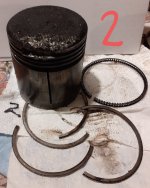
I measured the "lip" thickness at 7mm. That gives a mating surface area of about 44mm^2. That doesn't seem like much to me. Even with a sealant.

Permatex looks like they forgot about their one product then. https://www.permatex.com/products/g...tion-form-a-gasket-no-3-sealant-liquid-16-oz/
Both That permatex and wellseal seem to be very similar compositions. Atleast you can try the permatex "locally avalable/cnd tire sells it" and if it fails, then seek out wellseal. They also have the same "rated" temperature range also in their TDS, flash points, colour, and both alcohol based solvents. Ill take a risk and say they are likey very near identical products.
im actually going to pick up a bottle of the permatex next time im at the store. I personally never have seen a engine without any sort of physical "head gasket", but not dismissing the ideal of it. I will definetly try it out on these engines and see what the outcome is.
Last edited:
")