No correction intended or implied by me... I'm the least bright spark
")
round here.[emoji3]
I realise that
That could be the answer to either of those replies.:devil:
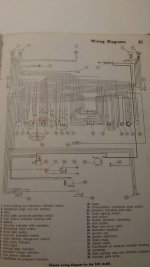
I can just about see that diagram and can see that wire direct from the battery to the fuse box. It is odd that they decided to go via the voltage regulator and then onto the fuse box.
You’ve got me started now! When you look at the individual fuses, all 8 amp.
Fuse 1 has main beam right 45W, left front parking light with indicator 25W, right rear parking light 5W. Total max current draw is 6.25 amps
Fuse 2 has the same but opposite sides. Same max current draw as above.
Fuse 3 & 4 are headlamp low beam 40W. One for each side. Max current draw is 3.33 amps each side.
Fuse 5 is remaining indicators with pilot lights, instrument lights, stop lights.
Fuse 6 is horn, wipers, rear view mirror interior lights.
Fuse 1 and 2 are obviously allocated these different loads, as the main beam isnt expected to be on for long periods of time, therefore they have stuck some additional loads on.
3 & 4 are higher loads but they are expected to be on for longer periods of time. Therefore they have each been allocated a single fuse each.
5 & 6 are again things that aren’t particularly high loads or on for prolonged periods of time.
Unprotected circuits are charging, ignition and starter.
If the ignition circuit is drawing 4 amps, there is potential if you have both dipped beams onto draw an additional 6.6 amps, parking lights another 1.66 amps maybe wipers on, I don’t know the power rating of the wiper motor but I doubt whether it draws more than 4 amps max. When those are all added up it comes to 16.2 amps. Everything else is used occasionally. Seeing as the voltage regulator also regulates the current at 16 amps and also the dynamo max continuous output is 16 amps. I would guess that the average current draw is below 16 amps. So 2 or 3mm squared wire would seem correct.
It’s taken me ages for me to work this out, so if it doesn’t make sense then I apologies.