Technical Fixing electrical wiring

Currently reading:
Technical Fixing electrical wiring

bonzoq

New member
Joined
Sep 24, 2023
Messages
6
Points
3
Location
Krakow
Hello everyone,

I have recently acquired a 1965 Fiat 500f and am new to the forum. I'm based in Poland, and the car was bought in Italy.

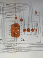
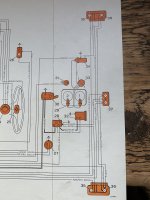
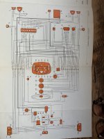
Now that the carburetor has been replaced, which got the engine running, it's time to fix the electrical wiring, which, over the years, I presume has been subject to a number of ad-hoc repairs, causing it to resemble proper Italian spaghetti.

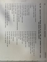
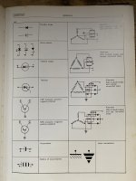
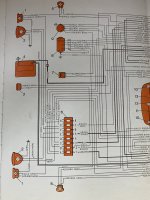
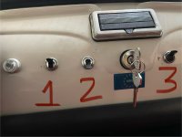
So there are three electrical switches on the front panel of the car (picture attached). My understanding of their function based on this diagram is as follows:
  1. Switch for instrument lighting
  2. Main switch for exterior lighting
  3. Wiper switch
Whereas in this very Fiat, they work differently:
  1. Main switch for exterior lighting
  2. Another main switch for exterior lighting including blinkers
  3. Wiper switch
I have the following questions:
  1. What are their actual functions?
  2. What is meant by instrument lighting?
 

Attachments

  • IMG_2642.jpeg
    IMG_2642.jpeg
    578.2 KB · Views: 80
Hi there - I can't help you with how your car seems to have been wired up but on my 1971 500L:

1. is instrument lights, which means a light in the instrument panel (speedo, etc.). It only works if the main lighting switch is on so, if the main lighting switch is off, flipping this switch doesn't do anything.

2. Main lighting switch turns on sidelights and rear lights only, if the lighting lever on the steering column is in its first position, and allows the instrument panel lights to be switched on as well if you want. Moving the column lever to the second position puts the headlights on low beam, third position switches on high beam.

Hope that helps a bit, and good luck sorting out your wiring :)
 
This helps a great deal and I'll try to recreate the wiring on your Fiat, which seems to be the original factory wiring. Thank you!
 
This is direct from the Official Fiat electrical manual of 1977, it covers older models and, whilst containing ‘generic’ wiring diagrams, it is a good basis for the ‘standardised electrical systems’. This is for the generic for 2cyl air cooled with dynamo
 

Attachments

  • IMG_4966.jpeg
    IMG_4966.jpeg
    2.2 MB · Views: 49
  • IMG_4967.jpeg
    IMG_4967.jpeg
    1.9 MB · Views: 46
  • IMG_4968.jpeg
    IMG_4968.jpeg
    2.1 MB · Views: 43
  • IMG_4963.jpeg
    IMG_4963.jpeg
    1.8 MB · Views: 44
  • IMG_4964.jpeg
    IMG_4964.jpeg
    1.8 MB · Views: 44
  • IMG_4969.jpeg
    IMG_4969.jpeg
    1.9 MB · Views: 45
  • IMG_4970.jpeg
    IMG_4970.jpeg
    1.8 MB · Views: 39
  • IMG_4971.jpeg
    IMG_4971.jpeg
    1.8 MB · Views: 42
  • IMG_4972.jpeg
    IMG_4972.jpeg
    1.7 MB · Views: 43
  • IMG_4965.jpeg
    IMG_4965.jpeg
    2.2 MB · Views: 47
Thank you guys for your input, I think I've managed to fix the wiring and reproduce the factory functions of all the switches.
 
Back
Top