Hi
You seen to have gone done the rabbit hole with your problem ( It has an intermittent immobiliser issue where the Fiat Code (immobiliser)
 light comes on and it will not start )
I see you are using a clone ELM 327 interface with your Multiscan software. ????
Do not do this only use the real one sold with the Multiscan software.
Multiscan advise this because of the many problems people have.
Do not use any other type of scan software / scan tools
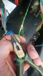
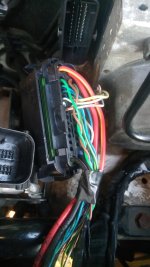
You need to get the e learn drawings and check / test all connections on the C lines.
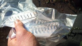
Be though with pin connections into plugs.
Start with the info I posted ( Graham O )
Can line problems will show all sorts of faults up which for the most are red herrings.
I found that at the hard way.
Stay with your first fault ( It has an intermittent immobiliser issue where the Fiat Code (immobiliser) light comes on and it will not start )
Graham O
You seen to have gone done the rabbit hole with your problem ( It has an intermittent immobiliser issue where the Fiat Code (immobiliser)
light comes on and it will not start )I see you are using a clone ELM 327 interface with your Multiscan software. ????
Do not do this only use the real one sold with the Multiscan software.
Multiscan advise this because of the many problems people have.
Do not use any other type of scan software / scan tools
You need to get the e learn drawings and check / test all connections on the C lines.
Be though with pin connections into plugs.
Start with the info I posted ( Graham O )
Can line problems will show all sorts of faults up which for the most are red herrings.
I found that at the hard way.
Stay with your first fault ( It has an intermittent immobiliser issue where the Fiat Code (immobiliser)
light comes on and it will not start )Graham O
")