Hi
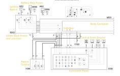
To save you wading through eLearn, below is the description of the instrument panel. I also attach a schematic, annotated in yellow by me. You will note that the instrument panel has two supplies, a permanent one via F53 and an ignition controlled one via F37. The power steering and engine management lamps get their supply via F37, and are earthed by the respective control units to illuminate the lamps. Since these seem to be working that suggests F37 is OK. F37 also supplies the brake lights via the BCM. I suggest you check out F53.
It's also possible that the instrument panel common ground (there appears to be just one) has gone open circuit or high resistance, this connects via a black wire on Pin 1 and then via the BCM to the central dashboard earth. The instrument panel connector may need a dose of proprietary switch cleaner and plugging/unplugging a few times.
From elearn:
The ignition-controlled power supply (INT) for the instrument panel E050 reaches pin 3 via the line protected by fuse
F37 of the junction unit B002; the direct battery supply arrives at pin 2 via the line protected by fuse
F53 of the junction unit B002.
The instrument panel E050 receives a reference earth at pin 1 via the connection with pin 36 of connector B of the Body Computer M001.
The instrument panel E050 is connected from pins 5 and 6 with the Body Computer M001 (pins 5 and 6 of connector B) and via the latter to the entire CAN.
The speedometer signal arrives from pin 23 of the braking system control unit M051 at pin 10 of connector A of the Body Computer M001, which repeats it for the instrument panel E050.
The electronic rev counter receives the engine rpm signal coming via the CAN from the engine management control unit M010, connected via pins 58 and 41 of connector A to the engine rpm sensor K046.
The fuel level gauge is controlled by means of signals coming from the level gauge located in the fuel pump assembly N040 - at pins 7 (positive) and 21 (negative) of connector C of the Body Computer M001 and from there via the CAN to the instrument panel E050.
The insufficient brake fluid level/handbrake warning light is lit up by a signal from the handbrake switch I040 that reaches pin 20 of connector C of the Body Computer M001 or from the signal from the brake fluid level sensor K025 that reaches pin 24 of connector A of M001.
The "engine coolant level" warning light is regulated by the engine coolant level sensor K026, connected to pin 9 of connector A of by the Body Computer M001.
The brake pad wear sensor (switch) K020 controls the warning light through the connection with pin 32 of connector A of the Body Computer M001.
The engine management control unit M010 also sends signals coming from the following units via the CAN (pin 83 and 84 of connector B) to the instrument panel:
- the insufficient engine oil pressure sensor (switch) K030, connected to pin 56 of connector A;
- the engine coolant temperature sensor K036, connected to pins 58 and 41 of connector A;
- the water in the diesel filter sensor K031, connected to pin 74 of connector B.
The braking system control unit M051 is connected, from pins 15 and 26, via the CAN line, to the engine management control unit M010, and via pins 14 and 25 to the Body Computer M001 (pins 48 and 49 of connector A) forwarding the signals described above.
There are two
direct connections for the instrument panel E050 to light up two warning lights: the EOBD warning light (pin 18) and the electric steering failure warning light (pin 17) which receive the earth signals produced by the auto-diagnostic system for the engine management control unit M010 (pin 71 of connector B) and the ‘Servotronik’ control unit M088 (pin 3) respectively.
See E5050 DIESEL ENGINES ELECTRONIC MANAGEMENT
See E7055 SERVOTRONIK DEVICE
The "Mode +" and "Mode -" controls (pins 5 and 6) located in the left control panel H091 send analogue signals to the instrument panel E050 (pins 13 and 16). Pin 2 of H091 receives the reference earth from pin 8 of connector B of the Body Computer M001.
The instrument panel E050 contains electronic modules that control the dimmed lighting adjustment.
See E2530 INSTRUMENT LIGHTING
The internal logic for E050 also manages the headlamp adjustment function: the panel sends a control signal to the motors in the headlamps from pin 7, whilst the enablement signal reaches pin 8 (dipped headlamps on). The control for the adjustment of the headlamps for unit H091 sends a signal to the instrument panel E050 (pin 14) each time the "+" or "-" buttons are pressed.
See E3080 HEADLAMP ALIGNMENT CORRECTOR
The Trip Computer zeroing button, located in the steering column switch unit H005 (pin 11 of connector A), sends an earth signal to pin 9 of the instrument panel E050.
See E4080 TRIP COMPUTER 

