Technical Citroen relay / ducato / boxer 230 fuel damper unit

Currently reading:
Technical Citroen relay / ducato / boxer 230 fuel damper unit

AdyRE

New member
Joined
Jan 2, 2022
Messages
16
Points
4
Location
Ripon
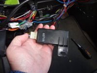
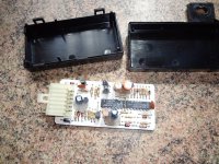
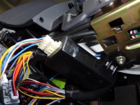
Hi all, just having ongoing issues with my fuel sensor / sender unit and wondered if anyone knows what voltages should be going to the fuel sender unit from the damper unit under the glove box area. I'm measuring 6.1vdc going to the fuel sender which is coming from the damper unit. I've got 2 x 12vdc inputs to the damper and 1 x 6.1vdc input which is then sent to the sender u it. I'm wondering should it be 12vdc to the sender or is this 6volts correct??
 

Attachments

  • m_dsc03384_108.jpg
    m_dsc03384_108.jpg
    41.3 KB · Views: 273
  • m_dsc03386_389.jpg
    m_dsc03386_389.jpg
    77.1 KB · Views: 89
  • m_dsc03379_175.jpg
    m_dsc03379_175.jpg
    50.5 KB · Views: 82
Hi

I would expect the sender and gauge connections to be sitting at something less than full 12V battery voltage. This "black box" looks like an earlier item than the "white box", judging from the vintage of the through-hole components. Are you able to read the part numbers on the IC's ? One looks like an LM something and the other looks like a HCF4066 Quad Switch. Nothing very complicated.

The most troublesome part is usually the connector, but some have tried re-soldering the joints on the board in case anything has worked loose. It's possible one or more of the electrolytic capacitors have dried out, and changing them could restore operation. They are the little cylinders with orange or black sleeves.
 
I had some success correcting a fluctuating reading from the same unit in my van. Resoldering the connector made no difference. I found the female part of the socket we're not making a good contact with the male pins. Taking them out one at a time and very carefully nipping them up seemed to do the trick. Clean and apply contact grease if they are tarnished. Sorry can't help with the voltages, I didn't measure them.
 
Hi

I would expect the sender and gauge connections to be sitting at something less than full 12V battery voltage. This "black box" looks like an earlier item than the "white box", judging from the vintage of the through-hole components. Are you able to read the part numbers on the IC's ? One looks like an LM something and the other looks like a HCF4066 Quad Switch. Nothing very complicated.

The most troublesome part is usually the connector, but some have tried re-soldering the joints on the board in case anything has worked loose. It's possible one or more of the electrolytic capacitors have dried out, and changing them could restore operation. They are the little cylinders with orange or black sleeves.
I'm going to remove it later on and have a closer look at what's what. I've got another issue anyway which I'm trying solve. My fuel sender unit is faulty. The resistance board on the float arm is snapped and won't read at all. Due to my van being a petrol finding a replacement is like finding unicorn dust. I bought one for a diesel and was hoping to nick the parts off to retro fit to my exiting one but my existing is a 2 wire level sender and the one I've got is a 3 wire one and I can't get it to read either which may point to an issue with the damper unit also.... I'm getting to my wits end lol
 
I had some success correcting a fluctuating reading from the same unit in my van. Resoldering the connector made no difference. I found the female part of the socket we're not making a good contact with the male pins. Taking them out one at a time and very carefully nipping them up seemed to do the trick. Clean and apply contact grease if they are tarnished. Sorry can't help with the voltages, I didn't measure them.
I'm going to have a look this week and see what's what. Could do we someone measuring the voltages and telling me what they should be haha
 
Could do we someone measuring the voltages and telling me what they should be haha
Next time I have call to be in there Is be happy to if I remember, but as you know it's a dash off job to get at it. I know it's very laborious but have you tried reconstructing the circuit diagram from the PCB tracks/components. From memory it is not a multi layer PCB so all the tracks should be visible.
 
Back
Top