Hi
I assume your vehicle is an X244 model Ducato (2002 to 2006). Both the central locking and the electric windows are controlled by the
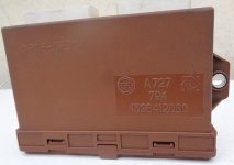
same M135 module, which pre-dates the Body Control Module system used from 2006 onwards. From memory this thing is in a brown plastic case with two multi-way connectors, under the dashboard. It is sometimes referred to as a "Comfort Control Module" which is a slight mis-translation of "Convenience Control Module". The same unit is used for the Peugeot and Citroen variants.
The module gets both ignition switched and permanent +12 volts via a number of Fuses, so I suggest you check the following in the main under-dash fuse board B002:
F24 5 Amp Control Lighting and Number Plate Lights via central control panel
F35 7.5 Amp Window and Locking Control via Ignition Switch
I also suggest you check the following in the optional under dash fuse board B101:
F38 20 Amp Door Lock Control direct from battery
F47 20 Amp Left Window Motor direct from Battery
F48 20 Amp Right Window Motor direct from Battery
Since F35 is used for both functions, this is the prime suspect. If all fuses are OK, you could try disconnecting and reconnecting the multi-way connectors to M135 to see if this forces a reset. One connector deals mostly with windows and the other mostly with locking, but they are both needed for full working.
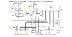
I attach a schematic for the electric windows and a description of electric window and central locking operation. These are from elearn but with my editing and additional captions. Unfortunately the schematic for electric windows is corrupted and therefore of no use.
244001769 - E3050 FRONT ELECTRIC WINDOWS OPERATIONAL DESCRIPTION
Operational Description
The electric window system is managed by control unit M135 (ABI). The control unit is ignition-operated - pin 8 connector B - and protected by fuse F35, housed in underfacia junction unit B002. An ignition-operated power supply is distributed from coupling junction D097E, to control unit M135, and also switches H044 - pin 2 connector A and B - and H050 - pin 2 -. Control unit M135 is connected as follows:
- pin 8 : raise control for left window motor N060;
- pin 9 : lower control for left window motor N060;
- pin 11 : lower control for left window motor from switch unit H044 - pin 3 connector A -;
- pin 10 : raise control for left window motor from switch unit H044 - pin 4 connector A -;
- pin 5 : lower control for right window motor from switch unit H044 - pin 3 connector B -;
- pin 18 : raise control for right window motor from switch unit H044 - pin 4 connector B -;
- pin 2 : lower control for right window motor from switch H050 - pin 3 -;
- pin 6 : raise control for right window motor from switch H050 - pin 4 -;
- pin 1 : raise control for right window motor N061;
- pin 3 : lower control for right window motor N061;
Controls H044 and H050 come with internal lighting that comes on when the side lights are turned on. The side light activation signal comes from control panel H090 - pin 12 connector C - and is distributed from junction D097E to the appliances. A light activation signal reaches control panel H090 - pin 2 connector A - from a line protected by fuse F24, located in underfacia junction unit B002.
Control unit M135 receives power directly from the battery at pins 15 and 16, from a line protected by fuses F47 and F48 located in optional underfacia control unit B101.
244001755 - E3040 CENTRAL LOCKING OPERATIONAL DESCRIPTION
Schematic not available (corrupted)
Operational Description
ABI control unit (electric window/door lock) M135 manages the vehicle door lock/release system. The control unit is supplied:
- Directly from the battery: via a connection between pin 8 connector B of M135 and pin 11 connector B of optional junction unit B101, protected by fuse F38, housed in optional junction unit B101;
- Key operation: via a connection between pin 7 connector B of M135 and pin 3 connector C of junction unit B002, protected by fuse F35, housed in junction unit B002;
Control unit ABI M135 receives and sends the following signals from connector B:
- pin 15 : input from coupling junction D097G - pin 6 - of door lock signal;
- pin 16 : input from coupling junction D097F - pin 6 - of door lock release signal;
- pin 4 : send door lock release control signal to coupling junction D097F - pin 1;
- pin 13 : connection to earth C015.
Coupling junction D097G manages the door lock signal. The closure control is received at pins 8 and 7 from front door locks N050 and N051 respectively - pin 4 -. Pin 1 receives a door lock signal from control unit ABI M135 that distributes to door locks N051, N050 and N054 respectively from pins 2, 3 and 4. Coupling junction D097F manages the door lock release signal.
The opening control is received at pins 8 and 7 from front door locks N050 and N051 respectively - pin 3 -. Pin 6 receives a door lock release signal from control unit ABI M135 that distributes to door locks N051, N050 and N054 respectively from pins 2, 3 and 4. Front door locks N050 and N051 are connected as follows:
- pin 5 : earth connection C020;
- pin 3 : earth signal transmission for door lock;
- pin 4 : earth signal transmission for door lock release;
- pins 1 and 2: door open/close motor power supply.
Double door lock N054 receives a motor control power supply for door opening/closure from coupling junction D097.