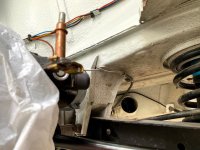
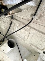
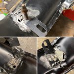
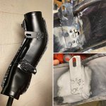
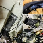
So I got my 126 starter cable in the mail, so I went to install the heater tube and ran into some problems - problems I think others have had before. I've read Peter's thread here, and came to the same conclusion more or less but wanted to socialize a planned fix. The brackets don't line up with the existing holes as Peter found out, and I re-discovered. Rather than go through the headache of re-clocking the brackets, I was thinking about drilling 2 holes through the flat portion of the body, about 6-8 inches apart. The bottom hole, I'd drill large enough for a socket+extension, while the top one will first be for a self-tapping screw to mark the position, followed by a riv-nut (assuming there's space). I'd fit some 1/4" rubber washers between the tube and the body to isolate it and get rubber body plugs for the bottom holes. Any thoughts on this course of action? I think it'd be a lot more straight-forward than fiddling with brackets. My main concern is working room with the control arm right there.
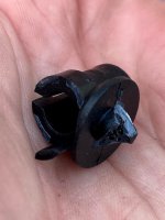
Also, the plastic clamp for the starter cable shattered as soon as I tried to twist it into the tube, so that started things off wonderfully. I'll have to get another one of those and flatten/thin the mounting point to ensure that doesn't happen again. In the meantime, I've bodged a fix using the old 500 starter cable clamp and the existing hole for the previous header flex tube clamp someone installed.
If none of this pans out, I suppose I'll wind up reinstalling the flex tube that was on the car beforehand.