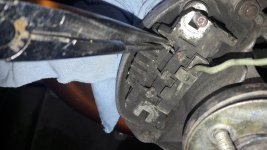
Done a few checks today, all terminals checked for condition, i also ,measured the diodes without removing them (Vout to the case should measure the rectifier so i found it withing limits but as Al mention above i am not sure if this measurement is reliable without unsolder each one diode.
I think that i can remove it in situ (i have first to remove my oil cooler ) and then take it out.
 I found that part locally so maybe give it a try, still reading about alternators..
The reason I kept suggesting testing the alternator using an oscilloscope was to avoid you having to do so much dismantling before being
absolutely certain that the fault lies somewhere in the diode pack (rectifier). I'm also conscious of the fact that the alternator on the 500 isn't the easiest to remove.... Plus, I don't want to cause you to possibly waste money on unnecessary parts either....
I've done some checking on just what can be ascertained from the waveform displayed on an oscilloscope when it's connected to the alternator output.
The waveform will normally take the form of a series of connected ripples.
If there are any voltage spikes on the trace, (possibly due to minor interference from the ignition system) try applying a load on the alternator e.g. turn on the headlights, the spikes should then disappear, if Alt. is ok.
Hash across the whole trace is often caused by poor brush contact.
Any variation from this regular pattern can indicate where the problem lies.
Depending on what this variation is, it can be determined whether e.g.
1) an exciter diode is open circuit, or 2) shorted,
3) a positive diode is open circuit, or 4) shorted,
5) a negative diode is open circuit, or 6) shorted.
(Some, but afaik not all alternators have these exciter diodes)
So use of an oscilloscope can check 3 +ve diodes, 3 -ve diodes, 3 exciter diodes (if fitted), check for good brush contact and output voltage, all without removing the alternator or any dismantling.
The 'Electronic Engine Analysers' that I mentioned earlier (Bosch, Crypton, Souriau? etc.) were very popular in the 1970's onwards - many main dealerships/larger workshops had them. (the signs for 'Crypton Tune-Up Available Here' used to be everywhere) They could also be used for a very fast and detailed inspection of the points based ignition systems, made finding a faulty component a doddle! (if you knew what you were doing
). It would be worth trying to find someone with a working example of such test equipment - it is literally a 2 minute test to check out all the alternator components listed above.
I'm sorry I can't scan and upload the various waveform patterns for alternator faults - but these waveforms are available in many older books on auto-electricity or auto-diagnostics.
Al.