Technical 500R Coil

Currently reading:
Technical 500R Coil

Joined
Sep 17, 2023
Messages
34
Points
68
Location
Midlands
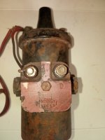
My 500R misfires when hot.

The coil does become pretty warm to the touch.

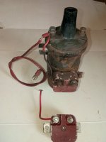
Coil resistance is 3.3Ohms, but there is also a red square in the side of it which the feed passes through - this has a resistance of 1.1Ohms.

I did put this coil on the car when I built it up (from parts). So should I have a 1.5Ohm coil, or is the installation correct, or should I be using the coil I have without the 1.1Ohm resistor?

All other aspects of the engine appear healthy. The misfire is present with two different carbs (one 26IMB, the other a 28IMB). Valve clearances correct, good compression I’m on both cyclinders ~110psi. Points gap and timing correct.

Any thoughts?

Thanks, Ray
IMG_8271.jpeg
 
My 500R misfires when hot.

The coil does become pretty warm to the touch.

Coil resistance is 3.3Ohms, but there is also a red square in the side of it which the feed passes through - this has a resistance of 1.1Ohms.

I did put this coil on the car when I built it up (from parts). So should I have a 1.5Ohm coil, or is the installation correct, or should I be using the coil I have without the 1.1Ohm resistor?

All other aspects of the engine appear healthy. The misfire is present with two different carbs (one 26IMB, the other a 28IMB). Valve clearances correct, good compression I’m on both cyclinders ~110psi. Points gap and timing correct.

Any thoughts?

Thanks, RayView attachment 465184
Others will give specific advice on your model, but in general terms, coils using a ballast resister with a 12 volt system have two wires on the SW (live) side of the ignition coil which in effect is a 8 volt coil. The theory is that when cranking the starter pulls down the voltage due to load, so the direct 12 volt supply to the coil is reduced to feed the 8 volt coil, once the ignition key is released that 12 volt direct supply is off and then the 12 volts is going to one side of the ballast resistor and then the reduced output is fed to the other wire on the SW side of the ignition coil to run at it's normal reduced voltage specification.
This should then under normal circumstances prevent the ignition coil from overheating.
The CB (contact breaker side of the coil goes to the distributor points as normal on a non electronic ignition system.
I was unaware of this setup on your model, so maybe someone else has thought it a good idea, others on Forum will know I am sure.
By the way if ignition is left on for too long with out engine running it will cause a standard coil to overheat, it also destroys the condensor and burns the points.
Another point is some coils are marked - and + instead of SW and CB, again in general terms with a modern alternator based system using negative earth set up then + would be the SW side and - would be the CB side as CB side goes to earth through the contact points. Usually reversed if dynamo set up as per the old days positive earth cars.
None of this applies to aftermarket electronic ignition systems of course.;)
 
Last edited:
Others will give specific advice on your model, but in general terms, coils using a ballast resister with a 12 volt system have two wires on the SW (live) side of the ignition coil which in effect is a 8 volt coil. The theory is that when cranking the starter pulls down the voltage due to load, so the direct 12 volt supply to the coil is reduced to feed the 8 volt coil, once the ignition key is released that 12 volt direct supply is off and then the 12 volts is going to one side of the ballast resistor and then the reduced output is fed to the other wire on the SW side of the ignition coil to run at it's normal reduced voltage specification.
This should then under normal circumstances prevent the ignition coil from overheating.
The CB (contact breaker side of the coil goes to the distributor points as normal on a non electronic ignition system.
I was unaware of this setup on your model, so maybe someone else has thought it a good idea, others on Forum will know I am sure.
By the way if ignition is left on for too long with out engine running it will cause a standard coil to overheat, it also destroys the condensor and burns the points.
Another point is some coils are marked - and + instead of SW and CB, again in general terms with a modern alternator based system using negative earth set up then + would be the SW side and - would be the CB side as CB side goes to earth through the contact points. Usually reversed if dynamo set up as per the old days positive earth cars.
None of this applies to aftermarket electronic ignition systems of course.;)
Thansk fro the insight. So it’s very likely that this coil arrangement has been taken from another car (Fiat 850?) which would have had two feeds to it - 1 during cranking and the second for normal running - and would have had a 1.5Ohm coil.

I’ll put the feed directly to the coil and bypass the 1.1Ohm ballast resistor and see if it make an improvement to the hot misfire.

If that doesn’t work I’ve got some new plugs on the way (plugs can be funny little fellas) and I’ve got a VW beetle that has no running issues that I can borrow a different coil from…
Test using a volt meter to be sure and maybe look up the specifications on that coil to be safe.
 
I've seen that type of coil with red block fitted to Fiats that have a rev-counter (tachometer) (e.g. 850 Sport, 124 Sport etc.) but not fitted to Fiats that didn't have a rev-counter (e.g. 850 Saloon, 124 Saloon etc.) which ties in with what @Toshi 975 has suggested.

However, I'm a bit embarrassed to admit I'm not sure exactly what the function of the red block is. But I don't think it's a ballast resistor for the ignition coil, I think it's something to do with operation of the the rev-counter - the cars I've seen had a brown/white wire going from one side of this red block to the rev-counter. Also, having checked a few wiring diagrams for Fiat cars fitted with rev-counters, this red block is not connected between the live feed to the ignition coil but is instead connected between the coil and the low-tension wire that goes to the distributor c/b points.
On Fiats with the red block, the originally fitted coil has terminals marked B+ (live feed from ignition switch) and D which goes to the distributor. One terminal of the red block is connected to the D terminal and the other terminal of the red block is connected to the lead going to the distributor.

While the coil mounting bracket and the red block in Op's pic look like Fiat items, the coil looks probably aftermarket (coil top terminals seem to be marked - and possibly +).
There were 3 makes of ignition coil fitted to Fiats of that era, = (Magneti) Marelli, Bosch or Martinetti, the only difference are the slight variations in secondary winding resistance (Marelli = 5500 to 7000 ohms, Bosch = 6500 to 8900 ohms, Martinetti = 6500 to 8000 ohms) - the primary winding resistance for all 3 makes of coil is 3.0 - 3.6 ohms, so Op's reading of 3.30 ohms seems just fine. All 3 of these coils use a 12v supply and do not use a ballast resistor.

Op's intention to try bypassing the red block sounds like the correct solution to the problem. Also, as stated above, the current coil with 3.30 ohm primary winding resistance should be fine to use (without the red block).
I am not familiar with rev counter systems but what you say appears to make sense, as the output wire from that red block looks like it wants to sit on the other side of the coil to be "comfortable" which when you zoom in is marked - (negative) so would be going to points if a negative earth system, but is actually bent towards the live side of coil, probably marked + (positive).:)
Does look like a mix and match set up.
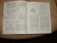
Sorry if this clouds the issue further, but found this in an old car manual, although seems to be related to electronic ignition, but does show wiring for a rev counter.
 

Attachments

  • DSCF1976.JPG
    DSCF1976.JPG
    469.6 KB · Views: 13
  • DSCF1974.JPG
    DSCF1974.JPG
    464.5 KB · Views: 12
Last edited:
I did some further checking and found these out of stock items, (note they're listed as 1.2 and 1.8 ohm) @ midwest-bayless.com :-


Fiat ignition coil Ballast Resistor.png


Fiat ignition coil Ballast resistor 1.8 ohm.png


Plus, searching through my little stock of old parts, I found a spare one that is marked 0.8 ohm.

It seems like I was wrong in saying it was wasn't a ballast resistor, so apologies for any unintended misinformation.
But why it is fitted on the distributor side of the coil instead of in the live supply to the coil is puzzling, although it would probably still limit the current flowing in the coil primary windings, plus there's no 2nd feed from the starter motor or st/mtr solenoid as found on a normal ballasted coil. I checked an official Fiat parts manual and it's not shown as a separate part or even listed although the ignition coil #4158493 is shown.
 
I did some further checking and found these out of stock items, (note they're listed as 1.2 and 1.8 ohm) @ midwest-bayless.com :-


View attachment 465289


View attachment 465290


Plus, searching through my little stock of old parts, I found a spare one that is marked 0.8 ohm.

It seems like I was wrong in saying it was wasn't a ballast resistor, so apologies for any unintended misinformation.
But why it is fitted on the distributor side of the coil instead of in the live supply to the coil is puzzling, although it would probably still limit the current flowing in the coil primary windings, plus there's no 2nd feed from the starter motor or st/mtr solenoid as found on a normal ballasted coil. I checked an official Fiat parts manual and it's not shown as a separate part or even listed although the ignition coil #4158493 is shown.
Either way it is the wrong part for this system, so needs testing and correcting, unless of course there is an extra wire behind the red one that we cannot see in the photo.:)
 
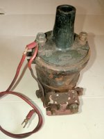
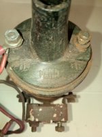
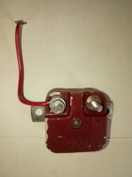
I've just been rummaging in my 'stores' (a.k.a. the garden shed) and found these - an ignition coil from a Fiat 850 Sport Coupe, as removed without disturbing the wiring connections, and a spare 'ballast resistor'.

IMG_20250422_154438.jpgIMG_20250422_154319.jpgIMG_20250422_154328.jpgIMG_20250422_154344.jpg

The coil top is marked D on the left terminal and B+ on the right terminal.
B+ is the live feed from the ignition switch, usually a blue/black wire.
The coiled red wire (non original colour, should be green?) is going from the D terminal on the coil top to the distributor.
There is also a single core (fairly rigid) red wire going from the Coil D terminal to the left terminal on the red block, this terminal is not marked, the other terminal on the red block, marked D had a brown wire that goes to the tachometer (revcounter).
According to the wiring diagram for this car, the coiled red wire should be connected to D on the red block, not D on the coil tower. (this car was a non-runner being dismantled for spares and had been 'worked-on'...).

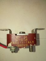
This is a spare red block, made by Magneti Marelli, which I now believe to indeed be a ballast resistor, it's as removed from a car and has the rigid single core wire still bent to follow the shape of the coil and to reach the coil D terminal, it's connected to the left hand unmarked terminal on the red block.
Only the right hand terminal is marked = D.
The top of the block is ink-stamped :-
REF 5A
9J - Ohm 0.8,
MADE IN ITALY,
(BREV)0
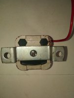
The rear of the red block seems to have a resistor sealed into a possibly ceramic? block :-

IMG_20250422_154357.jpgFiat ignition coil ballast resistor_IMG_20250422_154407.jpgRear view of ballast resistor for Fiat ign coil_IMG_20250422_154416.jpg
 
Last edited:
I once made the mistake of being the owner of a Fiat 126 BIS. It was equipped with a substantial ballast resistor which was located at the front, in the spare wheel well. Sufficient other things preoccupied me when owning that car, so I didn't trouble myself about the ignition arrangements. ;) But the car must obviously have had two electrical feeds from the ignition switch, one of which routed through the resistor.

Unless the ignition lock has been modified or replaced with a later version, I can't see how the car of @Fatcatvera is using this component as designed. If it is alternatively, somehow being used to modify a coil that has a different resistance to the originals I agree with @bugsymike that the simplest and most reliable thing would be to replace the coil with standard; there are plenty available at a reasonable price.
 
Thankyou all for your efforts in understanding the coil installation on my car.

The car came to me as a pile of parts, including the coil arrangement in the photo of my original post. The original coil fitted in that bracket didn't work, but was 3Ohm, so not knowing any better at the time I replaced it with a new 3Ohm coil which then gave me a spark and the engine would run.

I've now removed the 1.1Ohm ballast resistor from the coil feed but have yet to run the car hot (due to the weather) to assess for hot misfire. Now the coil will be seeing 12v instead of 9v it can only be better!

I'll feed back once I've assessed the car.

Ray
 
Back
Top