Abarth L
New member
- Joined
- Apr 9, 2010
- Messages
- 136
- Points
- 32
Yes, this is not under guides, I have tried countless of hours to no avail to get it done under the guides section.
_____________________________________________________
After about 2500 km's after rebuilding the engine I stopped at the Supermarket and the car just didn't want to start without any warning.
 Tip! Change sensor with new for engine rebuild.
Symptoms:
1. Verified timing.

2. Verified fuel pump system is working.

3. No spark.

4. ECU gave via Torque app "P0340: Camshaft Position Sensor "A" Circuit "

Duration: 2 -3 Hours
Difficulty: 3/5
Technical: 4/5
Section 1: First Step is to prepare the car.
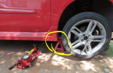
1. Remove the RH front wheel.
 NB! Safety first: use trestle or support, not just a jack.
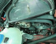
2. Remove the belt cover.
3. Remove the engine top cover.
Turn engine to TDC and mark pulleys
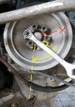
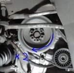
1. Turn the engine clockwise to TDC
 NB! Don't use the crankshaft bold to turn the motor (It is LH tread, you might loosen it!!)
I just use a 13 spanner over one of the Rife bolt and use the shoulder of the spanner as force area.
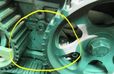
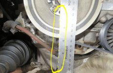
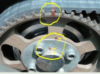
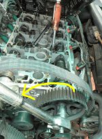
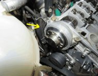
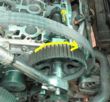
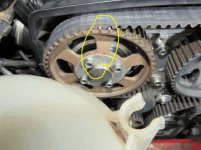
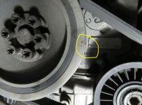
1a. Line up the hole in the pulley, now on the picture it is actually very easy the hole which also align with the Crank pulley in the back ground always face down to the centre of the bolt that hold the sump.
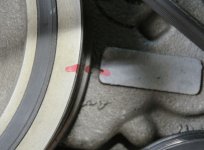
It also align with the LH straight line indent on the sump to the sensor, I tried to mark it in the pictures.
1b mark the pulley.
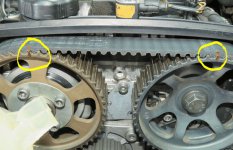
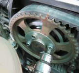
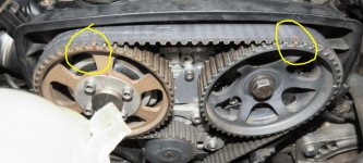
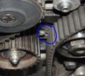
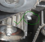
2. Mark the Inlet and Exhaust pulley's also the belt at those 2 points, it does not matter which teeth, I just take the 12 o clock position teeth.
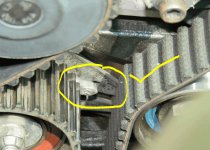
3. Verify the tensioner is still 100% correct, it should be, in my case after the 2500 km since the rebuild I was glad to see it is.
4. Mark the Inlet pulley shaft / plate vs pulley position.
Section 2: Remove Pulley's and Cam sensor
1. Loosen the tensioner.
2. Remove 4x Ribe bolts on Inlet Pulley.
3. Remove Inlet Pulley.
4. Remove LH plastic cover under Inlet Pulley.
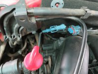
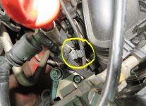
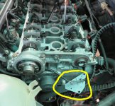
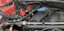
5. Unplug Blue plug of Cam sensor. (3 pin)
6. Remove cable from cable holder.
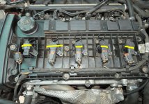
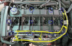
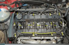
7. Remove 5x ignition coils.
8. Loosen cables attached to cam cover and move out of the way.
9. Loosen 12 cam cover bolds.
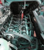
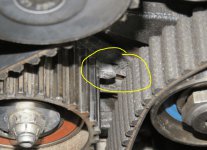
 10. Well I did not remove the breather pipes etc. It is not necessary I just lifted the Cam cover with a socket extension as temporary lever (look at image)
This helps with material maybe falling in, or damaging a clamp, hose or even breaking a one of the cam cover hose connection pipes.
 Be careful not to drop anything into the oil ports or even close by, this is a clean condition area!
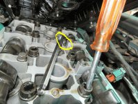
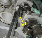
11. Now not everyone might agree with my method but really there is nothing wrong of how I "locked" the exhaust camshaft from turning anti-clockwise.
 I looked for a cam lobe that were close to a head support shoulder and inserted a flat tight fitting Allan key for the cam lobe to press against while I loosen the cam bolt.
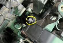
12. Remove the 2x Allan key bolts from the Hall effect phase sensor (Cam sensor)
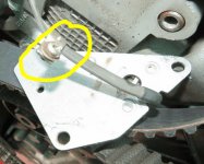
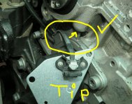
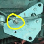
 TIP! Before I loosen remove the cam sensor I first remove the star (Phillip) screw clamp at the back of the plate so the flat cable is exposed more, then pull the sensor as close as possible to the known Water Pump area where there is a very thin tight opening, since the sleeve is now out of the way, the cable pull out much easier, so using same principle when installing the new sensor, eliminating any pinching.
Section 3: Install new Cam sensor and replace Pulley's
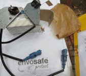
1. Install new sensor, Lightbulb, I use the procedure of removing the star screw and clamp to thread the cable to eliminate pinching, as described during the removal process and images.
2. Tighten 2x Allen Key screws with Loctite.
3. Pull the Sensor cable to its path and plug in.
4. Replace plastic cover LH. (2 screws)
5. Lock the Exhaust Cam again, now in the opposite direction with the Allan Key.
6. Torque the Exhaust Cam bolt. (Loctite)
7. Inspect Cam area for any tools or rags etc. before closing.
8. Replace Cam cover, 12x bolts, cables and ignition coils.
 Important to make sure the cover seal is in place everywhere, I also wiped the seal and surface area down first with a paper towel before refitting.
9. Pull the belt over tightly from the Exhaust Pulley to make and make sure the mark at the crank and exhaust match.
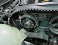
10. Now insert the Inlet cam pulley under Neath the belt aligned with its own mark and press upward till pulley fits over shaft.
11. Replace the plate washer and the 4x Ribe bolts, verify it align with the markings made, ( I used a punch and red marker during disassembly)
12. Verify Crank / Exhaust and Inlet marks correspond.
Section 4: Adjusting the Tensioner
 This part of the process is very important!
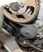
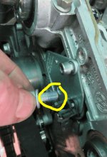
1. With all 3 pulleys on its marks, I tightened the tensioner just enough so it can slide with the screw driver wedging but has enough friction to stay in place. It took 3 times till I got it right.
2. Move Tensioner till it the pointer aligns to the dot (hole), now remember this you are now looking at an angle that can give you a parallax error so take your time!
3. Lock tensioner when correct position.
 The following steps is very important.
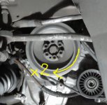
4. Turn engine 2x revolutions till TDC remember continues, never anti clockwise till mark. (Clockwise and not via Crankshaft Bold)
5. Verify tensioner mark in place (mine were not had to adjust tighter) also during engine rebuild I had to adjust again.
6. Turn another 2x turns to TDC in one direction, inspect tensioner.
You should be fine now.


Section 5: Testing and closing up.
1. So you can replace the engine cover and belt cover, I did not I first want to start and test for a day or two to verify frequently the tensioner is behaving, although not having a cover over the belt is not advisable since something might fall in and create chaos.
2. Start the car, don't rev high, monitor for noise etc.
Well if it were the sensor and the timing is done correctly it should start.
After I started my car there were no more ASR alarm , now confused, not sure how the logic on the ECU work??
Car sounded smoother, but proof is in testing.
So I took another economy run as my previous and wow my fuel consumption went from 11.3 to 12,2 for the same specific trip

The sensor might have been the reason why my Dyno graph is not so smooth and the guy from Bosh suggested a remap.
Hope this guide helps.
_____________________________________________________
After about 2500 km's after rebuilding the engine I stopped at the Supermarket and the car just didn't want to start without any warning.
Symptoms:
1. Verified timing.

2. Verified fuel pump system is working.

3. No spark.

4. ECU gave via Torque app "P0340: Camshaft Position Sensor "A" Circuit "

Duration: 2 -3 Hours
Difficulty: 3/5
Technical: 4/5
Section 1: First Step is to prepare the car.
1. Remove the RH front wheel.
2. Remove the belt cover.
3. Remove the engine top cover.
Turn engine to TDC and mark pulleys
1. Turn the engine clockwise to TDC
I just use a 13 spanner over one of the Rife bolt and use the shoulder of the spanner as force area.
1a. Line up the hole in the pulley, now on the picture it is actually very easy the hole which also align with the Crank pulley in the back ground always face down to the centre of the bolt that hold the sump.
It also align with the LH straight line indent on the sump to the sensor, I tried to mark it in the pictures.
1b mark the pulley.
2. Mark the Inlet and Exhaust pulley's also the belt at those 2 points, it does not matter which teeth, I just take the 12 o clock position teeth.
3. Verify the tensioner is still 100% correct, it should be, in my case after the 2500 km since the rebuild I was glad to see it is.
4. Mark the Inlet pulley shaft / plate vs pulley position.
Remove Pulley's and Cam sensor
Section 2: Remove Pulley's and Cam sensor
1. Loosen the tensioner.
2. Remove 4x Ribe bolts on Inlet Pulley.
3. Remove Inlet Pulley.
4. Remove LH plastic cover under Inlet Pulley.
5. Unplug Blue plug of Cam sensor. (3 pin)
6. Remove cable from cable holder.
7. Remove 5x ignition coils.
8. Loosen cables attached to cam cover and move out of the way.
9. Loosen 12 cam cover bolds.
This helps with material maybe falling in, or damaging a clamp, hose or even breaking a one of the cam cover hose connection pipes.
11. Now not everyone might agree with my method but really there is nothing wrong of how I "locked" the exhaust camshaft from turning anti-clockwise.
12. Remove the 2x Allan key bolts from the Hall effect phase sensor (Cam sensor)
Install new Cam sensor and replace Pulley's
Section 3: Install new Cam sensor and replace Pulley's
1. Install new sensor, Lightbulb, I use the procedure of removing the star screw and clamp to thread the cable to eliminate pinching, as described during the removal process and images.
2. Tighten 2x Allen Key screws with Loctite.
3. Pull the Sensor cable to its path and plug in.
4. Replace plastic cover LH. (2 screws)
5. Lock the Exhaust Cam again, now in the opposite direction with the Allan Key.
6. Torque the Exhaust Cam bolt. (Loctite)
7. Inspect Cam area for any tools or rags etc. before closing.
8. Replace Cam cover, 12x bolts, cables and ignition coils.
9. Pull the belt over tightly from the Exhaust Pulley to make and make sure the mark at the crank and exhaust match.
10. Now insert the Inlet cam pulley under Neath the belt aligned with its own mark and press upward till pulley fits over shaft.
11. Replace the plate washer and the 4x Ribe bolts, verify it align with the markings made, ( I used a punch and red marker during disassembly)
12. Verify Crank / Exhaust and Inlet marks correspond.
Adjusting the Tensioner
Section 4: Adjusting the Tensioner
1. With all 3 pulleys on its marks, I tightened the tensioner just enough so it can slide with the screw driver wedging but has enough friction to stay in place. It took 3 times till I got it right.
2. Move Tensioner till it the pointer aligns to the dot (hole), now remember this you are now looking at an angle that can give you a parallax error so take your time!
3. Lock tensioner when correct position.
4. Turn engine 2x revolutions till TDC remember continues, never anti clockwise till mark. (Clockwise and not via Crankshaft Bold)
5. Verify tensioner mark in place (mine were not had to adjust tighter) also during engine rebuild I had to adjust again.
6. Turn another 2x turns to TDC in one direction, inspect tensioner.
You should be fine now.


Testing and closing up
Section 5: Testing and closing up.
1. So you can replace the engine cover and belt cover, I did not I first want to start and test for a day or two to verify frequently the tensioner is behaving, although not having a cover over the belt is not advisable since something might fall in and create chaos.
2. Start the car, don't rev high, monitor for noise etc.
Well if it were the sensor and the timing is done correctly it should start.
After I started my car there were no more ASR alarm
Car sounded smoother, but proof is in testing.
So I took another economy run as my previous and wow my fuel consumption went from 11.3 to 12,2 for the same specific trip

The sensor might have been the reason why my Dyno graph is not so smooth and the guy from Bosh suggested a remap.
Hope this guide helps.
Attachments
-
 001.JPG65 KB · Views: 105
 -
 002.JPG84.2 KB · Views: 134
 -
 003.JPG68.3 KB · Views: 138
 -
 004.JPG47.2 KB · Views: 117
 -
 005.JPG49.5 KB · Views: 113
 -
 006.JPG64.8 KB · Views: 118
 -
 007.JPG86.7 KB · Views: 134
 -
 008.JPG81.7 KB · Views: 133
 -
 009.JPG77.5 KB · Views: 124
 -
 010.JPG43.2 KB · Views: 115
 -
 011.JPG58.3 KB · Views: 116
 -
 012.JPG60.2 KB · Views: 123
 -
 013.JPG62.9 KB · Views: 168
 -
 014.JPG75.5 KB · Views: 169
 -
 015.JPG67.1 KB · Views: 122
 -
 016.JPG107.2 KB · Views: 131
 -
 017.JPG99.4 KB · Views: 192
 -
 018.JPG73.7 KB · Views: 119
 -
 019.JPG106.2 KB · Views: 114
 -
 020.JPG61.1 KB · Views: 116
 -
 021.JPG67.7 KB · Views: 174
 -
 022.JPG71.5 KB · Views: 124
 -
 023.JPG51.2 KB · Views: 119
 -
 024.JPG33.4 KB · Views: 115
 -
 025.JPG82.5 KB · Views: 116
 -
 026.JPG17.2 KB · Views: 164
 -
 027.JPG36 KB · Views: 148
 -
 028.JPG57.4 KB · Views: 124
 -
 029.JPG15.9 KB · Views: 112
 -
 030.JPG36.7 KB · Views: 153
 -
 031.JPG70 KB · Views: 124
 -
 032.JPG62.1 KB · Views: 115
 -
 033.JPG51 KB · Views: 130
 -
 034.JPG59 KB · Views: 107
 -
 035.JPG63.7 KB · Views: 109
 -
 036.JPG28 KB · Views: 121
 -
 037.JPG22.6 KB · Views: 94
 -
 038.JPG28 KB · Views: 108
 -
 039.JPG30.9 KB · Views: 108

