Technical Camshaft position sensor malfunction

Currently reading:
Technical Camshaft position sensor malfunction

Mastus

New member
Joined
Apr 13, 2010
Messages
22
Points
5
Hi,

Been having problems with my Stilo 1,2 16V (2002) (again). Engine fault light is on and the fault code seems to be P0340 - Camshaft position sensor malfunction.

If I understand the eLearn manual correctly, it is located on the block near the spark plugs and the connector is on right hand side (looking the engine from the front).

Wires seem OK, the connector was not dirty and multimeter shows open circuit (infinite resistance) between all the pins leading to the sensor.

It seems that I need a new sensor (which costs a fortune) but is there anything special about installing new one? Take old one out and put new one back in? Is there anything more I could check, should there even be any "multimeter-measurable" resistance in the sensor when car is turned off. As I'm poor with cars, but some knowledge about electronics - Is there any faults to my reasoning?
 
IIRC the cam position sensor is a 'hall-effect device' it measures CHANGES in magnetic fields it works the same as an ABS sensor. if you turn the cam slowly the value across the sensor probably wont change where as if you have the engine running the sensor should 'pulse' or fluctute between open and closed circuits very rapidly.

check the Crank Position Sensor the engine looks at the relationship between the crank and cam and if the crank sensor is not picking up the right info then chances are it will throw a cam fault as you have described.

its possible that either sensor has shifted away from the sprocket leaving a large air gap rendering the sensor inoperable, try pushing them back in to see if it helps. (if the cam sensor is bolted in then this wont help, but its definately worth doing to the crank sensor)
 
Last edited:
Well the cam sensor is bolted on - but why should the ECU throw a crank sensor fault if the cam sensor is faulty? What I mean - if the cam sensor shows zero and crank sensor shows signal - doesn't the ECU show that cam sensor is faulty and vice versa?
 
the ECU looks for 3 things
1) Cam Position signals
2) crank position signals
3) the relationship between both (used to determine cam position in relation to crank position, for timing and fuel etc.)

if the crank sensor pics up incorrect readings from the crank, for instance every other peak on the crank (possibly caused by incorrect airgap or foreign objects on the crank sensor), and the cam picks up as it should then it may interpret this as the cam is spinning too fast, throwing a cam position fault

as far as i know the ECU checks to see if the crank sensor is operational (regardless if its data is erratic or not) if so it will use the signals to confirm engine speed and use it for a base to calculate what the cam position should be. even if the cam sensor responds with 'good data' the ecu will see it as a cam position fault.

have you tried cleaning and repositioning the crank sensor?
 
Last edited:
If the cam sensor is showing open circuit then it is dead. You might be lucky and have a broken wire or detached wire between the connector and the sensor but otherwise it is dead.

Try stabbing the two sensor wires insulation downstream of the connector and see if you still have open circuit between them as it might be poor wire connection at the connector

Cam sensor on a 1.2 is largely there to help it know which cylinder is on compression stroke at start up so it knows which cylinder to put sparks on and for noticing if there is a timing error between crankshaft and camshaft if someone has replaced timing belt incorrectly
 
Last edited:
Oh well...

300 kilometers later Stilo decided that the sensor is fine.
Got engine fault beeps 150 kilometers later (middle of driving) so it must be that the culprit is the wire after all.

Maybe better this way, the sensor seems to cost something like 150 euros here in Finland.

Never had a car before that fixes itself :)
 
Oh well...

All through fall CMPS has been mostly fine. Untily recently (1-2 weeks the engine failure has been on constantly).

So I stabbed the wires and watched what is going on.

Black wire (the lowest) seemed to be the supply voltage - which was OK. And as far as I know the signal wire is the middle one.

Which measured around 2-3 volts (varying) when engine is running. DMM showed a slight increase of the voltage when revving and I think it should work that way.

Does the voltage seem fine? (Can't find the oscilloscope probe and/or the OBD-reader right now :bang:)
 
Yes the centre pin is the signal. As it is a Hall effect sensor then it will produce a square wave signal with frequency relating to rpm so what you saw on your meter was ok as you were seeing an average of the square waves.

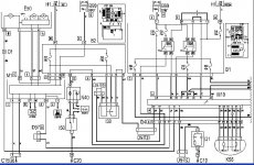
circuit 1.2 part 1.JPG

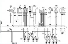
circuit 1.2 part 2.JPG
Be aware that the engine temperature sensor (ETS) shares the same ECU reference earth as the cam position sensor so if there is a fault in either circuit they can affect one another

 
Last edited:
Argh, the sensor has reference earth... I measured against body earth.

Measured again - and the result was the same. Around 2-3 volts depending of rpm.

Found the OBD-reader, and FiatECUscan threw the Cam sensor error with "invalid signal" with it. Cleared it -> start the car -> Beep beep engine fault -> measure the signal (it's ok) -> Reconnect OBD-reader and this time Cam sensor fault with "Signal low" -> Cleared it and then boom, everything is fine.

Started the car at least 5 times and wiggled the wire, and still all OK.

Had a cigarette and then started the car to back it up to the parking lot -> beep beep engine fault :mad:

If my reasoning is correct, so far we've established that the sensor is fine and it seems that the sensor connector near the engine block is too. Time to clean the ECU connector?
 
No I don't think you can say that the sensor is fine, your ECU has a different opinion:)

Ideally you want to be able to watch every bit of the sensor inputs and outputs with a scope
Watch voltage between pins 2 and 3 - signal and ref earth
is the square wave voltage clean ie going to 5v and to 0v? not somewhere in between
is the square wave frequency changing with rpm without drop outs?
if the peaks are going only to 3v maximum (which it might be) then it will trigger a fault of signal low

Watch voltage between pins 1 and 3
is it steady 5v through all rpm?
 
Last edited:
Between pins 1-3 voltage is steady around 14 volts...

Between pins 2-3... Square wave very noisy and not clean at all. Low period (should be zero) was around 2 volts and high period maxed out at just over 4 volts.

Waited for a while and suddendly - boom, clean square wave.

Restarted the engine and the signal was bad again... Checked my measuring multiple times.

It started to rain so I hurried to take the scope back inside -> Started the car and again Check OK :bang:

Signal is probably just on the verge of being recognized by the ECU.
 
Called the garage and they said (and I quote) "It's the sensor. Don't bother bringing it here, fix it yourself" :)

Ordered the bloody thing and changed it - It's been fine for over a week now so it was the sensor after all.
 
Back
Top