As many people will be aware certain model Seicento's and possibly some Cinquecento's do not come with a temperature gauge of any description. Instead they are fitted with a temperature warning light, or as I like to call it, "Oh Crap" Light.
The temperature warning light will only come on at extreme temperatures, as I know from experience. At this time the coolant will be boiling and will start to blow steam out of the pressurised cap, not really ideal, as by this point you risk serious engine damage.
To remedy this situation I set about fitting a temperature gauge to my car, which has been running for over a month as I write this article and has been working fine and providing a talking piece and most importantly, an accurate temperature read out.")
The temperature warning light will only come on at extreme temperatures, as I know from experience. At this time the coolant will be boiling and will start to blow steam out of the pressurised cap, not really ideal, as by this point you risk serious engine damage.
To remedy this situation I set about fitting a temperature gauge to my car, which has been running for over a month as I write this article and has been working fine and providing a talking piece and most importantly, an accurate temperature read out.
Tools and Consumables
A quick summary of the things you will need to do the job are detailed below.
- Screwdrivers / Spanners
- Utility Knife / Hacksaw
- Pliers
- Jubilee Clips (~30mm Diameter)
- PTFE/Teflon Tape
- Distilled Water (2 Litres)
- Engine Coolant (2 Litres)
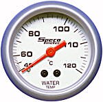
- Temperature Gauge (and sender if not included)
- Cable
- Coolant Hose Adapter (30mm OD)
- Jack / Axel Stands
- Multimeter
They look like:

If you would like to completely flush the cooling system while you are at it, seeing as you will be doing half anyway, them you will also need:
- Paper Gasket (or specific thermostat gasket)
- Gasket Sealant
How To?
There are variations on how the cooling and monitoring is performed and also what sensors and potential sensor locations there are in the Cento range. By following this guide, the installation does not interfere with any other system, and is therefore generic across the model range.
To start you need you car quite level and be able to get under the front of the car. Jack it up on a slight slope to achieve this, make sure the car is secure and safe, as you will be working under it.

Once its jacked up, locate the lower radiator hose clamp, grab the hose clamp tightly, and give it a good twist and wiggle to break it, you will replace it with a jubilee clip once done.

Slacken/remove the header cap and bleed screws (varies between model), and then remove the lower radiator hose, with a bucket waiting underneath.
Heres the empty system, and filthy water that came out (only 5 year old car, and didn't look too bad when in the header tank)!


Now flush a hosepipe through the header tank till water runs clear through the radiator, back flush it through the header tank, this gets all the gunk and dirt out.
At this point you may want to do a full flush, if so remove the coil packs, thermostat (where the large pipe connects to the side of the engine) and then flush through the engine as well. This is particularly important if changing colour or coolant type. Refit a new gasket, and seal with gasket seal.
The hose adapter is fitted in line with the main engine coolant outlet, remove the hose and cut a section out to accommodate the adapter.


Fit the adapter between both hose sections, secure with clamps and screw in the sender wrapped in PTFE tape. Refit the adapted section back to the thermostat and radiator inlet, secured with new jubilee clips!


Now make sure all your pipes are secure and bleed screws are open. Fill the coolant header tank with mixed coolant until it runs from the bleed screws and then refit them and the header cap.
NB. After a run and cool down you may need to bleed air from the bleed screws and refill with a bit more coolant.
The Electronics
Thats the more hands on part done, now all is needed is to wire it up and this is where all kits/dials and senders differ.
For my kit, i had a two wire sender, a gauge with 2x+Ve, 2x-Ve/GND, 1xGuage. The instructions were graphical only, and even with an electronics degree, made little/no sense!
I joined the two black wires, joined the two red wires, which left the follwing cables from the gauge, 1x+Ve, 1x-Ve and one temperature input. One of the senders wire goes to -Ve as well, the other goes to the sender input.
Hope you understand what I am explaining
Therefore I needed to find a +12V, and -Ve/GND where the gauge was to be fitted, on the dash for my application. One sender output was connected at the same point as the -Ve/GND and the other sender output went straight into the guage.
On the MPI Sei, the perfect place for this wiring to connect, is in the rev counter wiring, which is already fused by Fiat
If you observe following pictures, you can see the sender cables, and the Rev counter connector.
The Black Wire is -Ve, connect the gauge and one sender wire to this. The positive gauge wire needs to be connected to another wire!? Which one??!! I can't remember lol, but I don't think it was the red one. A quick check for a +12V with a multimeter will find it for you though! Check its +12v with the engine running, and that its constant 12V regardless of revs.
This ambiguity will actually make the guide more applicable to Cento wiring as well.

.jpg")
Now just mount the gauge and there you go
The Finished Product and Afterthoughts
#1.jpg")
Thats the finished product, hope yours goes as well as mine did
It all works great, and provides a reliable reading.
If I was to do it again, I would not get a smoked display as aren't easy to read in direct sunlight, but other than that I'd make no changes.
The sensor will only start to read once to thermostat starts to open, after a min or two of driving, but once it start to open it will give a constant temperature readout, which, on my car can range from ~75-90 degrees Celsius, depending on the situation.
Any questions, errors, queries or additions to the guide, just let me know
Thank you and good night,
Kristian