jonny2shotti
New member
- Joined
- Jul 9, 2018
- Messages
- 9
- Points
- 3
hi all,
im new here and hoping to find someone like myself that likes to know a part is truly faulty before replacing it.
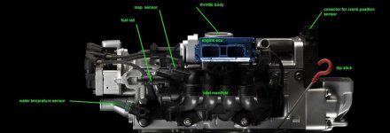
i have a 2006 1.2GP. can anybody tell me what resistance i should be expecting to measure from the MAP sensor at tickover and under load please?
any help will be gratefully received.
thanks in advance,
Jonny.
im new here and hoping to find someone like myself that likes to know a part is truly faulty before replacing it.
i have a 2006 1.2GP. can anybody tell me what resistance i should be expecting to measure from the MAP sensor at tickover and under load please?
any help will be gratefully received.
thanks in advance,
Jonny.