

blackburnsei
New member
- Joined
- Jun 4, 2005
- Messages
- 92
- Points
- 37
Heya, any of u chappies in lancs fancy giving me a lift (nah just u doing it LOL) to do a cam swap once i get my grubby hands on a 75 cam?
obv will pay generouslyish in beer or whatever floats ur boat.
Al
obv will pay generouslyish in beer or whatever floats ur boat.
Al
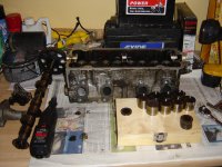
 ) and the follower. Shims sit in the tops of the follower caps..