The later edition of the 126 Haynes manual which has the supplement section to cover the 650 cars lists all of the specification changes and does not show any revision of the valve springs. However the manuals do not cover changes that took place as the improvements and production continued in Poland up to 2000. Cylinder head, ignition, camshaft etc were all upgraded so there is nothing to say that the valve springs were not changed at that time.


You are using an out of date browser. It may not display this or other websites correctly.
You should upgrade or use an alternative browser.
You should upgrade or use an alternative browser.
Technical Barrels/Pistons scoring. Salvageable?
- Thread starter JumpJet
- Start date
Currently reading:
Technical Barrels/Pistons scoring. Salvageable?
OP
OP
The Fiat Autobooks 853 has slightly different values for the outer spring than in the Fiat 500 edition. This may be put down to copy error, but at 57.3lb to achieve the same compressed length as was 42.1lb, this is significant enough to matter.
It suggests that the outer springs for the 126 engine may have been made to a different specification; I've not seen springs listed as specifically for the later engines, although I'm not prone to scouring the listings on some of the more exotic parts supplier site.
The only Autobooks for the 500 that I've seen is for the Nuova/F/D/N/L with the 499cc motors. Same for the "Workshop Manual" I have that while it says it covers 1957-73, it doesn't cover 594cc engines, only 499cc. I've never seen either book specifically for the 500R with the 594cc engine. The Autobooks 853 for the 126 posted above is for 1972-1976, published in 1976. Since the 500R ran from 71-76 as well, with the same size motor, I would venture a guess that the 126 & 500R, at least during that period, shared engine specs.
the hobbler
Distinguished member
- Joined
- Jul 25, 2012
- Messages
- 4,084
- Points
- 1,013
Hi Matt; as far as I am aware, the 500R and 594cc '126' engines are the same, with the exception of the carb. Fiat realised that, due to its lower weight, the 500R was quicker than the '126'with the same engine---so as it was the 126' that they had moved onto, they put a smaller carb (24IMB I believe) onto the 500R to slow it down!
The Autobooks 853 for the 126 posted above is for 1972-1976, published in 1976.
Since this thread made me realise that different publications may fill in the gaps in the general pool of information we have, I looked on Ebay for the Autobooks 853. There I found that the book had been reprinted several times, with an indication that it may have been slightly enlarged each time, to keep up with any changes.
With this assumption in mind, I've jumped and bought what might be the last edition possible, which covers 1972 to 1980. The Autobooks are a bit more technical and less pragmatic than Haynes. But the specification data provided is broader and better laid-out. So, with a bit of luck, it will reveal a few more obscure measurements for our future reference.
Attachments
Last edited:
OP
OP
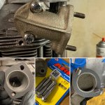
Little help confirming that I dorked this up, please...
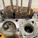
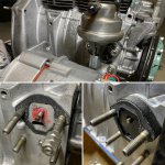
Got the head back from the machinist (yay) and went to put it on, finding that I'd have too much exposed thread for the cap nuts to thread fully on (boo) and still a ways to go to get the head seated (pic below). While I can't find this highlighted in any of the manuals, I'm thinking I installed the head studs in upside down - ie. the longer threads should be in the block side, while the shorter threads are for the head side. :bang: I probably didn't reference my teardown pics, assuming more thread makes more sense for the head side.
I'm looking at my pre-disassembly pics (below) and that appears to be the case, but just want to be 100% before I undo these.
:bang::bang::bang::bang:
Attachments
the hobbler
Distinguished member
- Joined
- Jul 25, 2012
- Messages
- 4,084
- Points
- 1,013
Doh! stupid boy (with apologies to Private Pike)---got the studs in upside down; long thread goes in the block for the full length of the thread.
OP
OP
Welp...at least there's enough sticking up to make it not too difficult to work with (fingers crossed). Off to swap them around.
OP
OP
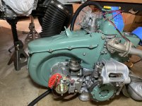
Fast forward 20 minutes and the studs are right again. Lesson learned. Got the head bolted on along with the exhaust manifolds. Mocked up some tin work to see how everything lines up and looks. Another L mistake to undo - the washers under the intake studs prevent the intake from seating, so tomorrow I’ll go undo the torques and fix that. Oh well.
Rather than go the stud route for the exhaust manifolds, I helicoil’d the threads and used high quality ARP hardware.
Rather than go the stud route for the exhaust manifolds, I helicoil’d the threads and used high quality ARP hardware.
Attachments

the hobbler
Distinguished member
- Joined
- Jul 25, 2012
- Messages
- 4,084
- Points
- 1,013
The washers under the intake manifold studs is a lesson I also had to learn--a thin washer as close to the diameter of the stud 'hex' as possible, and even then, on some manifolds you have to very slightly 'fettle'. I always find it easier to 'start' the 6mm bolt for the manifold before I tighten the 2x15mm nuts down. The engine is beggining to come together very well Matt--well done.
OP
OP
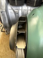
Good progress today (I hope). Got the motor mostly put together in prep for installation. I had to remove one of the alternator spacers (from the other thread) to get rid of some rubbing that occurred once everything was together and tight. Found a broken bolt down and behind the fan shroud that I hand't noticed prior. It wouldn't budge, so I let it lie. Ran out of M8x1.25 bolts, and found the drilled bolts for the head gasket are M10, where my head is threaded for M8, so I'll need to pickup some more bolts and rifle drill a couple.
So far, so good, but I really hope I don't have to replace the fuel pump anytime soon, as it'd be a PITA to remove because the studs prevent it from coming off w/o removing the alternator as well... which requires removing the tin, etc...
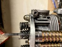
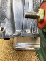
Which brings me to asking about the piece at the end of the fuel pump rod pictured below. I don't recall seeing anything like that on mine. I noticed when I went looking for the alternator vs. dynamo fuel pumps and now I'm worried I'll have to figure out that piece (and thus remove everything to get to it). Can anyone confirm/deny that there's a piece there I'm missing?
So far, so good, but I really hope I don't have to replace the fuel pump anytime soon, as it'd be a PITA to remove because the studs prevent it from coming off w/o removing the alternator as well... which requires removing the tin, etc...
Which brings me to asking about the piece at the end of the fuel pump rod pictured below. I don't recall seeing anything like that on mine. I noticed when I went looking for the alternator vs. dynamo fuel pumps and now I'm worried I'll have to figure out that piece (and thus remove everything to get to it). Can anyone confirm/deny that there's a piece there I'm missing?
Attachments
the hobbler
Distinguished member
- Joined
- Jul 25, 2012
- Messages
- 4,084
- Points
- 1,013
I have NEVER seen that 'end'piece' before,or seen that oart on an engine. There is a specific distance that the fuel-pump rod should extend past the end of the fuel pump spacer, which is adjusted by the number, and thickness of the gaskets you fit. Instead of studs, I tend to fit the fuel-pump with a couple of cap-head (allen) bolts (8 x 1.25mm thread, as long as required). Makes it a lot easier to remove/refit the fuel-pump should you ever need to, especially if you have a 126 specific fuel-pump which is angled at it's lower edge, (vis-a-vie the 500 pump) specifically to pull out over the alternator.
the hobbler
Distinguished member
- Joined
- Jul 25, 2012
- Messages
- 4,084
- Points
- 1,013
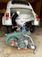
Had another look at you the pictures of your VERY smart engine Matt---you will find it a lot easier to fix the big air-intake hose to the ENGINE prior to fitment of the engine rather that the body. Once the engine is in, then slide the air-tube onto the bodywork---I hold it in place with a couple of big 're-useable' cable ties joined together (haven't found one long enough to do the job on its own)---makes for much easier fitment/removal.
Which brings me to asking about the piece at the end of the fuel pump rod pictured below. I don't recall seeing anything like that on mine. I noticed when I went looking for the alternator vs. dynamo fuel pumps and now I'm worried I'll have to figure out that piece (and thus remove everything to get to it). Can anyone confirm/deny that there's a piece there I'm missing?
There's nothing to see here.
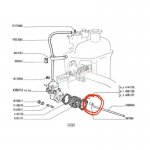
 It's not on the rod, it's the metal guide-bush which is inside the block to keep the push-rod aligned.
the hobbler
Distinguished member
- Joined
- Jul 25, 2012
- Messages
- 4,084
- Points
- 1,013
Spot-on Peter----part number:--987088--'bush' (or, to give it it's correct Italian name--boccola).
OP
OP
Thank you for the quick response gents! That's reassuring. While I didn't measure the pump rod protrusion prior to assembly, it was the pump+spacer that was on the motor prior an it had no supply issues. I think I'm going to bite the bullet and take everything apart, now that the motor is out, and replace the pump studs with hex head bolts. I just know that whenever the pump fails down the road, I will cuss myself for not making it easier when I could have. It looks like it'd still be a tricky R&R, but a long allen socket may get in there.
Lesson learned I suppose.
Tom - I just kind of stuck the intake hose there for the time being. I'm off to the hardware store today for (what I hope) is the last batch of hardware (before I tackle the throttle rod) and I'll be on the hunt for some BIG stainless jubilee clamps for the ducting, cold and hot.
Last edited:
While I didn't measure the pump rod protrusion prior to assembly,.
When you look at the explanation of the point at which to measure the protrusion and realise just how tricky it is to definitely identify that point, you might do what I do and give up trying.
If we all had the original pump as supplied by Fiat, I am sure this is a definite marker for the correct setting. But I have found that the myriad of optional pumps that I have available to me all have slightly different arrangements of the actuating-lever. Recently, when I wasn't quite getting an adequate fuel supply, it seems that the protrusion of the rod needed to be more than specified to make it work properly. I found that replacing with a pump with a slightly chunkier lever did the trick.
Therefore, I wouldn't worry that you didn't verify the measurement.
OP
OP
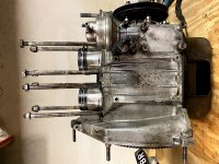
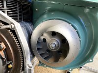
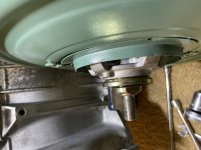
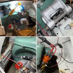
All good now. It was a lot easier the second time around to r&r the tin work. Pic below shows the pump rod distances I have and the final state with hex head screws. Now I’ll be able to replace the fuel pump without disassembling the whole motor. You can see the final gap I wound up with for the fan hub.
The car is back on the ground, gearbox filled, and only the motor install remains. ????
The car is back on the ground, gearbox filled, and only the motor install remains. ????
Attachments
OP
OP
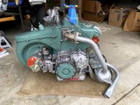
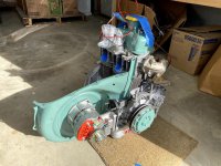
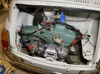
The engine is in! It took a little while to do single-handedly, but it’s in. Alternator is wired up, I wired in the distributor with a weatherpack connector for easier wire changes and/or dizzy replacement. A few final connections and adjustments remain, but ????it may run this coming weekend.
Any tips for initial clutch adjustment or ideas for what to do with the choke cable (my FZD is sans choke)?
Any tips for initial clutch adjustment or ideas for what to do with the choke cable (my FZD is sans choke)?
Attachments
the hobbler
Distinguished member
- Joined
- Jul 25, 2012
- Messages
- 4,084
- Points
- 1,013
Morning Matt; I also run a FZD sans choke cable and my proceedure is to give the throttle 2 or 3 slow depressions (which activates the accelerator pump), count to 10 and then crank. Unless it is very cold, which it has been up here in North Wales recently, the beast fires up, Sometimes I have to give the throttle another pump and then crank again and 'catch-it'. The reason for the count of 10 before cranking it is to give the fuel time to evaporate--vapour fires up a lot better than 'wet splodge'. I normally find that by the time I have gone about 1/2 mile down the road (first junction onto the main road) the engine is warm enough to idle properly.
For a brand new engine I would reccomend removing the plugs and cranking the engine until the oil light goes out, then refit the plugs and fire her up.
You might find that you have trouble pulling fuel through initially--I do if the engine has been out for any length of time. My trick is to remove the fuel line from the the pump (the 'in' line), put a can under the open fuel line and then pressurise the fuel tank until you can hear fuel coming out of the fuel line, and then quickly reconnect the line to the pump.
Clutch adjustment----1-3/8 to1-9/16in at the pedal--(35 to40mm) of free play at the pedal.
Well done---let us know how the first crank-up goes
OP
OP
Won't crank... little help please?
Got everything together and adjusted, filled with oil, and tried to crank 'er to build oil pressure and now I've got an issue with the starter (I think). I bench tested it before install, but it could've died at first attempt. Before I remove it to test again, I thought I'd ask the smart folks around here.
Video of the first try:
Start Attempt Video
It only cranked ~1" of pulley travel and died. All subsequent attempts blank out all the instrument lights and there's no sign of life from the starter. I've checked the engine ground strap and see a good ground all over the engine. I took the alternator wiring out of the loop, but no change. It didn't blow any fuses. I've tried disconnecting the coil and distributor as well to take them out of the loop.
I feel like I'm missing something obvious here. Are there any in-situ troubleshooting steps I should try before pulling the starter?
Much appreciated!