Technical Wiring route from throttle pedal to ECU

Currently reading:
Technical Wiring route from throttle pedal to ECU

cmac

New member
Joined
Sep 4, 2021
Messages
4
Points
3
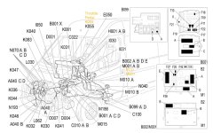
I want to trace the wiring from the throttle pedal all the way to the ECU because I'm 99% sure there's a broken / damaged wire along the way. Is there any document that shows where this is routed through the bulkhead and engine bay, or do I just have to play hunt the colour combination?
 
Hi

The layout diagram in eLearn isn't wonderful, but might help. As far as I know the 6 throttle pedal wires run direct to Connector B on the ECU, i.e. there are no intermediate junctions or connectors. Faults in wiring are often in the first and last couple of inches near the connectors, unless there has been chafing at some intermediate point.

If you can find a "hands free" way of joining an ohmmeter to the connector pins each end, you can use the audible continuity feature and listen while you bend and flex along the length of the loom. This can show up intermittent wire breaks that are much harder to see just looking at the display. If continuity checks out OK, it may be a good idea to then check insulation resistance from wire to wire and wire to chassis ground to see if anything is shorting.
 

Attachments

  • X250 Engine Management Components.jpg
    X250 Engine Management Components.jpg
    201.6 KB · Views: 520
Back
Top