You are using an out of date browser. It may not display this or other websites correctly.
You should upgrade or use an alternative browser.
You should upgrade or use an alternative browser.
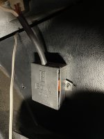
Technical What is this small black box?
- Thread starter Scoooch
- Start date
Currently reading:
Technical What is this small black box?
Could be anything...
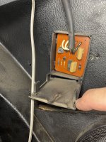
Can you retype the numbers on the chip? Perhaps that would show some results on the internet.
Can you retype the numbers on the chip? Perhaps that would show some results on the internet.
Scoooch
Member
Looks like a standard IC ,,, Cd4001cn mm5601anCould be anything...
Can you retype the numbers on the chip? Perhaps that would show some results on the internet.
Looks like a latching timer, designed to turn something off after a preset time. Wires are quite chunky, so perhaps a mirror/or rear screen heating circuit. (having a stab in the dark here) so does your vehicle have any of these? Are you able to trace the wires?
Scoooch
Member
I guess emissions maybe? I plan on tracing at some point - the wiring goes up behind the glove box along that lower support rail (behind the dash).Looks like a latching timer, designed to turn something off after a preset time. Wires are quite chunky, so perhaps a mirror/or rear screen heating circuit. (having a stab in the dark here) so does your vehicle have any of these? Are you able to trace the wires?
...It could perhaps be a timer for the intermittant setting on the wipers?
Can I ask what makes you think emmissions?
Can I ask what makes you think emmissions?
Scoooch
Member
Wiper timer is a SOLID suggestion. I think you may be on to something there!!! I am going to test this out when I get home this evening!...It could perhaps be a timer for the intermittant setting on the wipers?
Can I ask what makes you think emmissions?
I was thinking emissions: recirculating valves are triggered on specific events and timing. That was my approach,
Does it have remote locking? I'd be surprised, but it does look like it might be a receiver.
Tracing the wiring, is their a connector plug reachable? Disconnect it and see what stops working.
Tracing the wiring, is their a connector plug reachable? Disconnect it and see what stops working.
It's a NOR gate:Cd4001cn
A NOR gate delivers a high output only when neither of its inputs receives a high signal. In simpler terms, it provides a false output if any or both inputs are true. This behavior makes NOR gates fundamental in constructing logical circuits and forming the basis for more complex operations.
Doesn't sound to me like wiper timer. But I can be mistaken, it's too late for me for such logical thinking
This was what I noticed as well, made me wonder if I was an immobiliser of sorts or something that turns on a light when either door is open? Looks like the package has two NOR gates. It’s pretty basic logic, so I have to wonder if it’s a “module” of sorts for a dash function. Maybe a chime for leaving a door open or not putting on a seatbelt.It's a NOR gate:
A NOR gate delivers a high output only when neither of its inputs receives a high signal. In simpler terms, it provides a false output if any or both inputs are true. This behavior makes NOR gates fundamental in constructing logical circuits and forming the basis for more complex operations.
Doesn't sound to me like wiper timer. But I can be mistaken, it's too late for me for such logical thinking
Could also be something like that. But the wires look thick for such usage.This was what I noticed as well, made me wonder if I was an immobiliser of sorts or something that turns on a light when either door is open? Looks like the package has two NOR gates. It’s pretty basic logic, so I have to wonder if it’s a “module” of sorts for a dash function. Maybe a chime for leaving a door open or not putting on a seatbelt.
Scoooch
Member
From another discussion I am having elsewhere:
"I took mine off over 40 years ago. It was the seat belts, key buzzer and\or door chime, can't remember which but certain they were annoying."
"I took mine off over 40 years ago. It was the seat belts, key buzzer and\or door chime, can't remember which but certain they were annoying."
Scoooch
Member
None of those audio indicators work on my vehicle regardless. PO must have removed the piezo or it's dead (assumptions).
I thought that myself, but then remembered back in the 70s they would use 40 amp wire for everything.Could also be something like that. But the wires look thick for such usage.
Are you interested in getting a photo of the other side of the circuit board? That would make the circuit function easier to work out. As mentioned previously, its a pretty simple circuit, so I'm sure between us all, we can work it out. (Maybe)
I did spot an extra red wire hidden away... would love to know what's on the end of the white wires.
I did spot an extra red wire hidden away... would love to know what's on the end of the white wires.
Are you interested in getting a photo of the other side of the circuit board? That would make the circuit function easier to work out. As mentioned previously, its a pretty simple circuit, so I'm sure between us all, we can work it out. (Maybe)
I did spot an extra red wire hidden away... would love to know what's on the end of the white wires.
I'd say the red spot is not a wire, but the color of the middle of the three vertical elements in the center, from which the 1st from the right is definitely a resistor.
There is a red wire in there somewhere, you can see it coming out of the top of the bundle in the first picI'd say the red spot is not a wire, but the color of the middle of the three vertical elements in the center, from which the 1st from the right is definitely a resistor.
Ha, you are probably right. I was looking at the PCBThere is a red wire in there somewhere, you can see it coming out of the top of the bundle in the first pic
My guess is that the two transistors form a discrete Darlington pair, to switch a larger current (or put the smaller transistors base current into a workable parameter).
The Zener diode probably clamps the voltage into a region that all the components can use.
So when the circuit is energised, it with charge one of the capacitors, which will put the logic gate output on/off depending on how the circuit is configured, after a time the capacitor will discharge turning ouput through tranys off.
Just guessing here, but perhaps someone can offer another concept/idea.
Seeing the other side of the circuit board may enable a better prognosis.
The diodes are bugging me. Four diodes are normally there to create a rectifier, but its already DC so what's occuring?
Latching with NOR gates, made me think about astable oscillators, which requires two diodes per pair of NOR gates and produces a square wave. So a high frequency wave to control power output through the trannies, or a slow frequency to restart the wipers after a given delay
As the IC is a quad NOR gate device, that uses about 80% of the components....
So I'm going to hazard a guess that it's either two speed fan controller, or intermittent wiper switch.
Or.... neither of the above


As the IC is a quad NOR gate device, that uses about 80% of the components....
So I'm going to hazard a guess that it's either two speed fan controller, or intermittent wiper switch.
Or.... neither of the above
Similar threads
- Replies
- 7
- Views
- 328


