Technical Radio connector has no power & Relay question

Currently reading:
Technical Radio connector has no power & Relay question

Do you need help unlocking your radio?
Get your code instantly using our radio unlock service 🔓🎶

Jack100

New member
Joined
Aug 16, 2022
Messages
7
Points
1
Location
Zeewolde
I have just bought a 1996 Ducato camper with some electrical mess.
The radio is not working, I checked the ISO connectors and the battery voltage line stays 0V.
Apart from that, the signal line from the light switch which switches on the headlights is not
coming through to the dash display. Checked that line as well, no voltage.
That caused the instrument lights to stay off, so I bypassed that line.
Of course now the "lights on" indicator is always on. I prefer the original way though.

I have downloaded the service manual from this forum.

I can understand circuit diagrams, but it is vague where which component is located..

My questions:
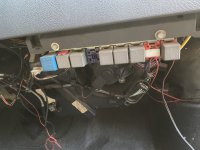
- does anyone know which relays are shown on the photo and what function has the missing purple one?
- any suggestions on how I can identify these (or any) relay in the car?
- has anybody else had similar electrical problems and if os, what was the cause?
- has anyone some sort of map how the cable tree is laid out in the car and where each (or most) components/
connectors/relays are located?

Any help is appreciated
 

Attachments

  • Fiat Ducato relays under glove compartment-1.jpg
    Fiat Ducato relays under glove compartment-1.jpg
    2.9 MB · Views: 1,648
Any help is appreciated
I'm not sure how much help i'm gonna be here , but i currently also have my dash in bits , year 2000 , x230 L14 , based Hymer . I've just finished a general tidy of the wiring , courtesy of previous owners , and now am fitting a new non standard radio . The relays bank is troublesome , in so much as there are no markings to indicate what does what . My layout is pretty much the same as yours , except i don't have any blank receivers .
Now what i can tell you for sure , is that two of the grey relays , each control the rear fog and front fog lights (if you have them) . I'm led to believe , another two control the headlight dip functions , one for each side , which is not uncommon practice in commercial vehicles , and there's one for the 4 way flashers . Now the interesting point i would make here , is that i suspected it to be the red relay which you appear to have missing . The large blue relay , i suspect is for the heater , due to the current capability , and i'm also led to believe , there is a further one for the horn , but i can't confirm that one just yet . However , it is a circuit i'm working on , as i'm converting to a twin horn installation . The engine fan relays are under the bonnet , so you can forget about them . They should be on the top offside of the radiator , under a plastic box , however there is a question over where the indicator relay/flasher unit is . I've been led to believe it's behind the instrument cluster , but i've not seen any sign of such to date , so i seriously doubt this . It is however possible , it's part of the four way relay , but i've been unable to test my theory , as my batteries are removed at present . Another troubling aspect on my van , is i also believe there is a further relay , that controls the split charging , and fridge operation on 12v . I've not found that either , though i have found a fuse on the d+ wire , which seems to lead to a large black box on the offside firewall , in the engine bay , but i can't be 100 percent sure of that at this stage . This wire would be the trigger for the relay to activate , but space under the bonnet is not a strong point of this van .
The radio is wired direct to fuse , i think 7/8 , but as this is ignition controlled , many motorhome owners wire direct to live . Normally this is the battery itself , however another source of constant power , is headlights , and it's not unheard of , to connect into this circuit for the likes of a radio , cigarette lighter , etc . Neither are a clever move , but it's still done . I found a hash up on my hazard warning switch connections . I suspect something like a gps was once connected there , judging by the wires left . The connections were made by someone who didn't really understand (or care) electrics , and was poorly installed . When it was removed , he just cut the wiring free , and left it . He struggled with this installation , as first off he drilled into the heater collection box to run the wire . Then running the wire a different way , put a screw through an alarm wire .
One final note is the instrument lighting , it's controlled by fuse 1 , and neither this or the radio have any relay connections .

So , what i would suggest with the faults you mention , well your principle problem to my mind appears to be the lights . The fact your radio is also not working , further suggests to me , it could well have been connected to the lighting circuit . Check your headlights work , both beams , high and low . Few motorhomes are driven at night , so it could be you have lost , high beam on one side . It's also rarely checked during an mot ! . Check your fuses , there are four , 2 for low beam / side light , 1 for each side , and 2 for high/main beam , again 1 each side . Failing that check your wiring , start at the switch , the most likely place for a radio connection .
Thanks for your extensive reply.
I found out in my car from checking the voltage and checking the downloaded service manual from this site:
Fuse 1 is for the voltage that is pernanently active. Used for clock, alarm lights, and radio.
Fuse 7 is for “contact switch on”, another wire to use for the radio so it can switch off and slide the display inside, when the contact switch is turned off.

Thanks for your insight about the relays. I have no heater so maybe that explains. Still I am figuring out where all camper utilities are led to and which fuse(s) protect that.

All lights function correctly.

When following leads I discovered that the ISO plug for the radio was only partially wired.
And following more leads I found the original ISO plug for the radio. Tied up and tucked away.
Plugging that into the radio kicked it alive.

Some “technicians” can make a mess out of thr wiring.

I will follow the lead for the “lights on” indicator to see where it is disconnected.

And after that clear up the rest of the mysterious mess.

Thanks again for your answer.
 
I'm not sure how much help i'm gonna be here , but i currently also have my dash in bits , year 2000 , x230 L14 , based Hymer . I've just finished a general tidy of the wiring , courtesy of previous owners , and now am fitting a new non standard radio . The relays bank is troublesome , in so much as there are no markings to indicate what does what . My layout is pretty much the same as yours , except i don't have any blank receivers .
Now what i can tell you for sure , is that two of the grey relays , each control the rear fog and front fog lights (if you have them) . I'm led to believe , another two control the headlight dip functions , one for each side , which is not uncommon practice in commercial vehicles , and there's one for the 4 way flashers . Now the interesting point i would make here , is that i suspected it to be the red relay which you appear to have missing . The large blue relay , i suspect is for the heater , due to the current capability , and i'm also led to believe , there is a further one for the horn , but i can't confirm that one just yet . However , it is a circuit i'm working on , as i'm converting to a twin horn installation . The engine fan relays are under the bonnet , so you can forget about them . They should be on the top offside of the radiator , under a plastic box , however there is a question over where the indicator relay/flasher unit is . I've been led to believe it's behind the instrument cluster , but i've not seen any sign of such to date , so i seriously doubt this . It is however possible , it's part of the four way relay , but i've been unable to test my theory , as my batteries are removed at present . Another troubling aspect on my van , is i also believe there is a further relay , that controls the split charging , and fridge operation on 12v . I've not found that either , though i have found a fuse on the d+ wire , which seems to lead to a large black box on the offside firewall , in the engine bay , but i can't be 100 percent sure of that at this stage . This wire would be the trigger for the relay to activate , but space under the bonnet is not a strong point of this van .
The radio is wired direct to fuse , i think 7/8 , but as this is ignition controlled , many motorhome owners wire direct to live . Normally this is the battery itself , however another source of constant power , is headlights , and it's not unheard of , to connect into this circuit for the likes of a radio , cigarette lighter , etc . Neither are a clever move , but it's still done . I found a hash up on my hazard warning switch connections . I suspect something like a gps was once connected there , judging by the wires left . The connections were made by someone who didn't really understand (or care) electrics , and was poorly installed . When it was removed , he just cut the wiring free , and left it . He struggled with this installation , as first off he drilled into the heater collection box to run the wire . Then running the wire a different way , put a screw through an alarm wire .
One final note is the instrument lighting , it's controlled by fuse 1 , and neither this or the radio have any relay connections .

So , what i would suggest with the faults you mention , well your principle problem to my mind appears to be the lights . The fact your radio is also not working , further suggests to me , it could well have been connected to the lighting circuit . Check your headlights work , both beams , high and low . Few motorhomes are driven at night , so it could be you have lost , high beam on one side . It's also rarely checked during an mot ! . Check your fuses , there are four , 2 for low beam / side light , 1 for each side , and 2 for high/main beam , again 1 each side . Failing that check your wiring , start at the switch , the most likely place for a radio connection .
Some insights to share after digging deep into the wiring and the service manual from this site (Fiat Ducato service manual 1991-2002):
- it took me some time to realize that there are some “duplicate pages” which depend on the exact car model
- most pages do not include wire color information, although the legend for colors is present. Where you see colorcoding, it usually is incorrect (or so it seems)
- as a page shows a vehicle function, there are quite some duplications between pages. Especially the fuse part. As a single fuse can protect several circuits at the same time.
- the instrument unit with gauges and indicator lights is hard to find.
- the radio and cigarette lighter are mentioned in the list of numbered items, but I did not find any on the schematics.
- several pages show the electrical schematics on the left side and the wiring layout on the right side. So on such a page everything occurs twofold.
- the non-engine fusebox is in the glove compartment and has a legend with icons that are quite well interpretable. Some took more studying, but with the help of the schematics and a Voltmeter to confirm, it can work out well.
- camper utilities like water pump, fridge, lights, toilet and extractor hood are nowhere to be found in this document

If anyone has any info on these missing pieces, I am happy to receive them.
 
If anyone has any info on these missing pieces, I am happy to receive them.
First off , camper van electrics are generally quite specific to make , so the first question i gotta ask , is what model is your van . I'm guessing it's not a Hymer , else you should have found the Elektroblock by now . This is the main power management system , used on most continental vans , including all Hymer related vehicles . Similarly a second system known as the Sargent power management system is used on a wide variety of British vans . Both these systems have engine and solar charging circuits for the battery , even monitoring electric intake , battery charging , and fridge control while connected to the mains via the ehu . These unit's also supply power for fridge control on the move from the 12v circuit , and all domestic circuits whilst parked up , backed with a fuse panel . A small number of vans (largely home builds) , have no management system to speak of at all . Their circuits are largely independent , with no monitoring what so ever .
Being as i own a Hymer , my own system is an Electroblock ebl99 , and in all honesty , this is the only system i may even be able to help with . But even here care should be exercised , as there are actually two versions of this particular model , a 16a , and 18a .

I also recently downloaded the manual from this site myself , and though it does cover the mechanical side better than my hard copy . I do have to admit , to being more than a little disappointed with the wiring section . Yes some pages appear to be duplicated , but be careful these vans were built under licence by several manufacturers , each having their own little variations , so don't just write them off . Citroen , Peugeot , even Vauxhall have all had a stake , and even Alfa and a few others have all had their hands in the pot at some time . My own van has an Iveco engine . However , manuals for these vans are really quite rare , so you have to be thankful for any head start you can get . Manuals are the most sought after question on any British forum , and i'm sure it's the same your side of the ditch . It's even worse with the modern versions , and all the sensors , and extra functions those vans come with .

Now to answer your remark in your first post to me , yes you're quite correct , even technicians can make a mess of an installation . I have removed a couple of nasty's that i suspect Hymer themselves may have installed , one being on the aforementioned d+ wire . I'm no expert , but i have been messing with auto-electric's for close on 40 years , from a wide range of vehicle manufacturers . I've made many mistakes in the past , but now have learnt , pretty much what works and what doesn't . The problem is , vehicles get more complicated all the time , and motorhomes are probably the worst . I'm being stretched with mine , and have had to retool several times to cover certain jobs .
 
==================================================================================================
- camper utilities like water pump, fridge, lights, toilet and extractor hood are nowhere to be found in this document

If anyone has any info on these missing pieces, I am happy to receive them.
Do not expect to find information relating to these items in a manual relating to the Ducato or other base vehicle, as they will have been fitted by the converter. If any information is available it will be in the converters manual. The converter has not been named, but if this is available try a web search quoting converter and model.

@airwave has mentioned Schaudt, and Sargent as manufacturers of motorhome electrical systems, but seems to be unaware of the popular CBE range of accessories. There are others. However it may be that some of these makes had not been introduced when your vehicle was converted. This leads to the possibility that the habitation electrical system has been built from individual components.

Popular locations for 12V distribution systems incude under seats, under beds, and in wardrobes. Fridge and split charge relays are often located in the engine bay of older vehicles.
 
There are others.

Hi mate , yeah your quite correct , and thanks for making that point .

I did have a Cbe online catalogue on my last computer , as i was looking into a product they market . However , i lost that when the computer packed up earlier in the year . I never looked at the rest of the catalogue , as i wasn't in need of anything else , so , i'll be honest , and say i was unaware they had complete systems , though frankly i'm not surprised . I do know there are other brands , but when i offer advice , i try to limit myself to information i have personal knowledge of . It struck me that Schaudt and Sargent are the two most likely brands the op may have come across , especially as he is over in France . I use a Schaudt system myself , and though i have heard of the Sargent system being mentioned in the past , i couldn't offer any assistance with one , as i've never actually used it myself . I'm still a relative newcomer to motorhoming , but i've been messing around with mechanical , and electrical systems for nigh on 40 years , motorcycle , automotive , and marine . Yet i'm still no expert or even try to claim to be such .
 
Thanks for all the info, I’ll dive deep into the mentioned locations to find the distribution box of the camper utilities.
I did find a 50A fuse with a wire that goes under the van in the direction of the fridge or further back. I did not follow that as I ran into..

A SERIOUS PROBLEM: when I switch on the ignition, the power dies off in a matter of seconds.

It is not a straight cut off, more like dying off in 1-3 seconds. And after waiting for some minutes I can try again.

Like some thermal fuse, which I don’t expect to be there.

Battery is good, voltage is and stays 13.0V and does not decrease during this situation.
The voltage after the main fuse (not the 50A one, but the big black block) is still 13.0V.
At the ignition switch, the voltage is 12.0V (!)
And after switching on the contact (no starting yet) the fans blow for a moment and then die off. The voltage on the ignition switch goes to 3V when I switch off the ignition. I don’t want to start a fire so I am cautious in thermal seeming errors.

Is there indeed a thermal resettable fuse between the main fuse and the ignition switch?

The schematics show; battery - main fuse - ignition switch.
If this is true, the culprit would be the wire between fuse and switch.

It is difficult to follow this main wire as it goes behind the dashboard. So it’s not easy to check if there is anything in between those 2 points.

Any suggestions are highly appreciated.
Except for the fact that you say that the battery voltage stays at 13V, I would have deduced that the vehicle battery is completely discharged.. Are you actually measuring the battery voltage across the battery terninals when you turn the key? This would need either long test leads, or an assistant. 13V is slightly high for a charged 12V battery at rest. Can you check your meter on another battery/vehicle?

As an alternative to measuring the battery voltage, you could monitor the voltage drop between the battery +ve, and the ignition switch. This test would confirm your supicions.

Another possibility may be a poor earth connection. Check for voltage drop between battery -ve and chassis.
I used long leads and measured on the battery itself, to eliminate all doubts.
The camper has a solar charger and I think the main battery is being charged as well.
I did check my meter on a voltage source, it is within 2% accuracy at this range.

Voltage drop between battery and chassis changes a few mV when I switch on the ignition.
Voltage drop between battery and plus of the ignition switch jumps to about 12V.

Before reading on, please note that I use crocodile clips that I connect to the batteries screwt on the cable terminal.
So nearly no force is applied to the cables.
So when checking again, all of a sudden I have full power again.

After this I applied some pulling force and wiggling to the cables in order to locate a break or weakness. Both at the ignition switch and at the battery.
No change, the system continues to work.

Still I will dig deeper because when this happens when driving, accidents could happen as all electricity is dead. So no alarm ligths, no headlights and maybe even the engine shutting down as well.

Any more of these very useful suggestions?
 
Hi Jack100

As you have found, the circuit information for these vehicles is not good, and sometimes unreadable.

The symptom you describe (power dying away over a few seconds) sounds like a poor/corroded contact (joint) somewhere. The resistance, combined with the current flowing through it, generates localised heat. As the contact temperature rises, the contact resistance increases and generates even more heat etc. A heater blower is quite "hungry", on maximum speed it could need 25 Amps. Headlamps need about 10 Amps. I think pre 1999 the blower current passed through the ignition switch, and post 1999 it was taken before the switch. Difficult to be sure with the poor schematics. Maybe the ignition switches couldn't take the current reliably ?

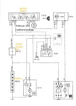
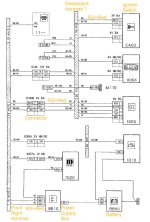
The line from the battery positive pole to the input side of the ignition switch is a fairly simple one. It passes through the Power supply Box BB10 and a connector IC40B between one harness and another. The wire colour is Red (RG) throughout. The wires rarely give problems, but any contact like a plug and socket, a fuse and fuseholder or even a bolted/clamped joint can all become poor. I suggest you visually follow along the whole path and check/clean/tighten every single contact. Look for any signs of heating (black/brown colour, deformed plastic) or contact faces that are not shiny metal. Use a small mirror under the dashboard, and take off trim if you have to. Make sure that "someone" has not added their own extra joint somewhere along the line !

If working properly, there should be much less than 1 volt drop between the battery positive post and the input blade of the ignition switch when high current is being drawn for example Fan on #4.

I attach two diagrams for a standard vehicle (No Camper additions) to which I have added my own captions in Yellow.

As you know, we are working from poor data and Fiat often changed things, so use this as a guide only !
 

Attachments

  • X230 Ignition Switch Schematic.jpg
    X230 Ignition Switch Schematic.jpg
    95.3 KB · Views: 101
  • X230 Ignition Switch.jpg
    X230 Ignition Switch.jpg
    144.5 KB · Views: 147
As your diagram suggests the presence of a main battery fuse, is it possible to find this fuse and test either side of it?

Another possibility, since the vehicle is a camper with the habitation battery on mains charge. You have suggested that the vehicle (starter) battery is also receiving charge. My campervan has CBE electrics and the vehicle (starter) battery is also charged from mains at about 2A via a PTC thermistor. This would take a short time to heat up and drop the voltage as you describe. Schaudt Electroblocks use a similar technique. If not already done, try testing with mains charge off. It could be that the vehicle system is only receiving a supply via this route due to a blown fuse or bad connection.

I noted that my esteemed fellow forum member, @Anthony489 has just posted the results of some hard work on his part. That gives you more routes of enquiry to follow.
 
Hi Jack100

As you have found, the circuit information for these vehicles is not good, and sometimes unreadable.

The symptom you describe (power dying away over a few seconds) sounds like a poor/corroded contact (joint) somewhere. The resistance, combined with the current flowing through it, generates localised heat. As the contact temperature rises, the contact resistance increases and generates even more heat etc. A heater blower is quite "hungry", on maximum speed it could need 25 Amps. Headlamps need about 10 Amps. I think pre 1999 the blower current passed through the ignition switch, and post 1999 it was taken before the switch. Difficult to be sure with the poor schematics. Maybe the ignition switches couldn't take the current reliably ?

The line from the battery positive pole to the input side of the ignition switch is a fairly simple one. It passes through the Power supply Box BB10 and a connector IC40B between one harness and another. The wire colour is Red (RG) throughout. The wires rarely give problems, but any contact like a plug and socket, a fuse and fuseholder or even a bolted/clamped joint can all become poor. I suggest you visually follow along the whole path and check/clean/tighten every single contact. Look for any signs of heating (black/brown colour, deformed plastic) or contact faces that are not shiny metal. Use a small mirror under the dashboard, and take off trim if you have to. Make sure that "someone" has not added their own extra joint somewhere along the line !

If working properly, there should be much less than 1 volt drop between the battery positive post and the input blade of the ignition switch when high current is being drawn for example Fan on #4.

I attach two diagrams for a standard vehicle (No Camper additions) to which I have added my own captions in Yellow.

As you know, we are working from poor data and Fiat often changed things, so use this as a guide only !
Hi Anthony,

thanks for your explanation.
What I see when I follow the red lead from the dashboard back to the battery, I encounter a black box. The lid can be removed and it is basically a mounting point for both the ignition switch wire and the fuse wire. Then "next in line" is a U-formed black box with 2 thick red wires and on the box it says FUSE, so fair to suppose this is a fuse. The other wire goes to the battery directly.

I checked both on the + of the battery and on the joint in this connection box. No drop at all on these points when the ignition is switched on.

This connection box, is this BB10? Or is there another box? If so, what does it look like and where is it usually located?

Thanks for the schematic fpages, I work likewise. Figure out how a piece of wiring goed and then make notes.
(Interestingly there is "radio" mentioned on the legend, but no page whatsoever that shows the radio's wiring.
 
As your diagram suggests the presence of a main battery fuse, is it possible to find this fuse and test either side of it?

Another possibility, since the vehicle is a camper with the habitation battery on mains charge. You have suggested that the vehicle (starter) battery is also receiving charge. My campervan has CBE electrics and the vehicle (starter) battery is also charged from mains at about 2A via a PTC thermistor. This would take a short time to heat up and drop the voltage as you describe. Schaudt Electroblocks use a similar technique. If not already done, try testing with mains charge off. It could be that the vehicle system is only receiving a supply via this route due to a blown fuse or bad connection.

I noted that my esteemed fellow forum member, @Anthony489 has just posted the results of some hard work on his part. That gives you more routes of enquiry to follow.
I did locate the fuse and it is in a box that is not easy to open. But it has 2 red wires, one goed to the battery, the other to a connection box.
I checked the voltage drop between those two points, the drop is a few mV.

A PTC is also something that I thought of. Especially as it took longer for the power to shut off when I took a longer time to leave it alone (let it cool).
As the battery does not drop in voltage at all when the ignition switches off, I think it is fair to say that the battery is strong.
Otherwise the voltage would drop by hundredths of millivolts.

Thank you for your insights
 
I did try to answer this morning , but my internet was craggy , and screwing around . My first thought was also the battery , but after reading the posts since , i can see it's gone beyond that , and become more involved .
To be honest , i'm also dealing with problems of my own . So as you seem to be in good hands , and quite frankly there's really not much more i can add , i'm gonna back out here , and deal with those .
 
I did locate the fuse and it is in a box that is not easy to open. But it has 2 red wires, one goed to the battery, the other to a connection box.
I checked the voltage drop between those two points, the drop is a few mV.

A PTC is also something that I thought of. Especially as it took longer for the power to shut off when I took a longer time to leave it alone (let it cool).
As the battery does not drop in voltage at all when the ignition switches off, I think it is fair to say that the battery is strong.
Otherwise the voltage would drop by hundredths of millivolts.

Thank you for your insights
The fuse is not shown on the diagram posted by Anthony489, presumably a later addition. Are you certain that the fuse is OK? Perhaps repeat voltage drop connections as above, but also check for continuity through the fuse. Best to diconnect battery negative when carrying out continuity test - no stray current to upset meter.

Have you disproved my idea about a feed from the mains charger, by testing with mains switched off?

If you are drawing current from the starter battery, than I would expect the terminal voltage to drop slightly. The battery will have some internal resistance.
 
Do you need help unlocking your radio?
Get your code instantly using our radio unlock service 🔓🎶
Back
Top