

Mshibonium
New member
Hello guys... I have a good one here.
I am super new to the forum and I could not find my problem in the discussion tabs, hence my post. But I have benefitted by reading two or three threads before for which I am thankful. Now over to my saga...
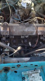
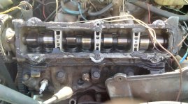
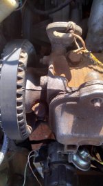
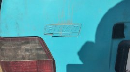
I am working on a Fiat Uno Lisence (made in South Africa) that is running on a 1301cc (?? Maybe 1372cc) carburetor engine (see photos), 4 door not fuel injection that was towed to me about a week ago. The car had wiring issues which I sorted out (see pics) but now I have a slight problem with the the TWO ignition modules installed on the car. Yes, there are two modules. It appears to me that someone fiddled with the car and was stumped and had it towed to me instead.
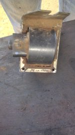
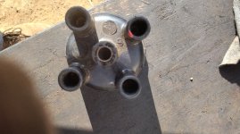
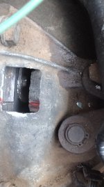
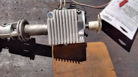
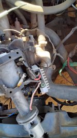
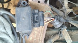
Now, here is what I think is wrong... The ignition module (which Alex dubs as "the famous finned module") installed on the distributor picture1, is NOT for this engine but for the Fiat Uno 1116cc. Secondly, the other module, picture2, is for this engine but is either dead or the car caused problems for the owner in the past and the 1116cc module was fitted in an attempt to alleviate the problem. I have taken plenty of other pictures to make my saga a bit short. I believe that if the finned module is wrong for the engine, then I would have to rewire the orange wire from the ignition switch to go directly to the coil 15 terminal and from 15 terminal to fiinned module (as per diagram by Dragon Man which I have attached) as I believe that too ignition modules are too much!! and that the modules might send unsychronised signals to coil and cause misfires and early coil failure... but I stand corrected.
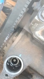
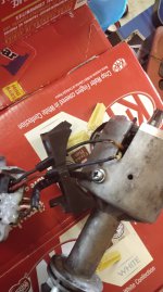
The picture of the distributor rotor was taken at TDC, can you guys confirm that the dizzy is set correctly? I think so.
Thirdly, if the finned module fiited to the dizzy is wrong, then the ignotion coil is also wrong!! Am I making sense guys? Or are the coils for the 1116cc, 1301cc and 1372cc the same? The Haynes manual I got says otherwise.
Fourthly, is the rotor on the dizzy compatible too?
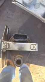
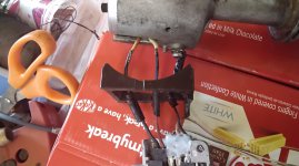
Lastly, I decided to inspect the wires (G+ and W-) going to the pick up sensor inside the distributor... and I found that insde they change colour into ORANGE and WHITE . Now, the wire is corresponding with the WHITE wire inside the dizzy is actually connected to G+ (the red wire) and the ORANGE one inside the distributor is connected to W- from module (see pictures). Is that right?
Summary:
Please comfirm the correct module
Please confirm timing and rotor
Please confirm coil type
PS: The owner says the car once started but was not running well. The owner says the car had a hard start, which could be the carb or module problems, wiring, etc. Many mechanics are afraid of the Uno in South Africa, I am not I believe most mechanics don't understand the little fella.
Humbly in need
Mshibonium, in RSA
I am super new to the forum and I could not find my problem in the discussion tabs, hence my post. But I have benefitted by reading two or three threads before for which I am thankful. Now over to my saga...
I am working on a Fiat Uno Lisence (made in South Africa) that is running on a 1301cc (?? Maybe 1372cc) carburetor engine (see photos), 4 door not fuel injection that was towed to me about a week ago. The car had wiring issues which I sorted out (see pics) but now I have a slight problem with the the TWO ignition modules installed on the car. Yes, there are two modules. It appears to me that someone fiddled with the car and was stumped and had it towed to me instead.
Now, here is what I think is wrong... The ignition module (which Alex dubs as "the famous finned module") installed on the distributor picture1, is NOT for this engine but for the Fiat Uno 1116cc. Secondly, the other module, picture2, is for this engine but is either dead or the car caused problems for the owner in the past and the 1116cc module was fitted in an attempt to alleviate the problem. I have taken plenty of other pictures to make my saga a bit short. I believe that if the finned module is wrong for the engine, then I would have to rewire the orange wire from the ignition switch to go directly to the coil 15 terminal and from 15 terminal to fiinned module (as per diagram by Dragon Man which I have attached) as I believe that too ignition modules are too much!!
and that the modules might send unsychronised signals to coil and cause misfires and early coil failure... but I stand corrected.The picture of the distributor rotor was taken at TDC, can you guys confirm that the dizzy is set correctly? I think so.
Thirdly, if the finned module fiited to the dizzy is wrong, then the ignotion coil is also wrong!! Am I making sense guys? Or are the coils for the 1116cc, 1301cc and 1372cc the same? The Haynes manual I got says otherwise.
Fourthly, is the rotor on the dizzy compatible too?
Lastly, I decided to inspect the wires (G+ and W-) going to the pick up sensor inside the distributor... and I found that insde they change colour into ORANGE and WHITE . Now, the wire is corresponding with the WHITE wire inside the dizzy is actually connected to G+ (the red wire) and the ORANGE one inside the distributor is connected to W- from module (see pictures). Is that right?
Summary:
Please comfirm the correct module
Please confirm timing and rotor
Please confirm coil type
PS: The owner says the car once started but was not running well. The owner says the car had a hard start, which could be the carb or module problems, wiring, etc. Many mechanics are afraid of the Uno in South Africa, I am not I believe most mechanics don't understand the little fella.
Humbly in need
Mshibonium, in RSA
Attachments
-
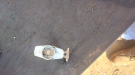
 Oil pump drive dog.jpg426.3 KB · Views: 423
 -
 Ignition coil side.jpg742.9 KB · Views: 274
 -
 Ignition coil front.jpg672.5 KB · Views: 331
 -
 Engine side.jpg634.4 KB · Views: 261
 -
 Cam TDC.jpg698.7 KB · Views: 280
 -
 Rotor top view.jpg4 MB · Views: 246
 -
 Dizzy cap.jpg1.1 MB · Views: 301
 -
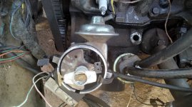 Dizzy at TDC in car.jpg782.8 KB · Views: 535
 -
 Cam sprocket at tDC.jpg678.9 KB · Views: 250
 -
 Crank TDC.jpg553.8 KB · Views: 235
 -
 Back badge.jpg4 MB · Views: 292
 -
 Module finned module on dizzy side.jpg779.9 KB · Views: 415
 -
 Module wires.jpg765.7 KB · Views: 610
 -
 Module wires side.jpg667.7 KB · Views: 731
 -
 IMG_20230902_092752.jpg791 KB · Views: 544
 -
 IMG_20230902_101632.jpg558.9 KB · Views: 326
 -
 Pick up sensor wire connection.jpg4 MB · Views: 339