

fiatfactory
New member
I started my conversion quite a while ago, but as is often the case with these sorts of projects, life gets in the way, and things get put on hold....
These are some pictures I took a while ago, and have only recently developed and scanned. I will get more pics soon, as I will be removing the entire setup to copy for a T/C installation into the RacerX. (see other thread this X19 forum) I may even make up some jigs so I can replicate the setup for anyone keen on going the T/C option.
here is a (rather long) description of how I did it...
*Twin cam conversion*
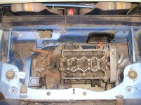
It took a while to decide on the engines final position. I have taken utmost care to ensure the handling will not be unduly affected by the weight change. I figured that the front of a Lancia Beta is quite evenly weighted so I’d try to position the engine as it was originally, but only tilting it as much as I needed to get clearance for the carburettors. Tilting the engine too far back would shift the weight bias even further rearward. We don’t want that now, do we, so the engine/transmission assembly is mounted with only a 10-degree rearward tilt. I also spent a lot of time making sure the gearbox outputs were in line with the hub centres, so the axles would be absolutely straight when the car was running level.
Next step was to install the five-speed type hubs, front and rear, allowing me to use the larger wheel bearings. The later Ritmo/Uno type bearings last a lot longer at the front and the rears are now the same bearing as the Lancia Beta uses, so these are designed to support the increased weight. The later type hubs also gives you the drive flange at the rear instead of 128 style C.V. joints
The engine is positioned so the ends of the drive flanges of the gearbox (’m still using the Beta idle axle) are equidistant (exactly) If you don’t get the measurements right at this stage, the CV joints will bind at a point in the suspension travel. This allows me to use two standard short side 5 speed x19 axles to complete this part of the conversion, (neat huh), they match the Beta inner pattern and fit the std 5 speed rear hub. These are precisely in line with the drive flanges in both planes with the car sitting level, I have seen conversions with the axles skewed and the C.V. joints constantly running through a large angle, bad practice IMO.
As I said the bodywork only needed a small amount cut out to clear the transmission casing, from the left chassis rail, right about where the standard flex brake line mount is inside the wheel arch. I’ve had to move this bracket also, otherwise the brake rubber line will rub on the gearbox end casing. Also the alloy of the gearbox casing needs to be sculpted in a few places to provide a little extra clearance. You have to cut the body or the engine just won’t sit in the right place. I simply plated every thing up very neatly, making it all look very standard with lips in the right places. I also added some plating to the upper surfaces of the chassis-rail. I also gusseted it up where it connects to the forward engine bay transverse chassis member.
You do however, need to give a bit more clearance than the standard rear control arm will give to the gearbox. This involved cutting away, mostly from the upper part, sufficient material. I then boxed the arm, enclosing the open side. This should give it sufficient strength, but to be sure I added the amount I had cut from the inside edges of the arm back onto the outside of the arm as well.
The car uses a Fiat Regata 100s water pump. This is held to the engine block with 8 x 1.25 bolts and is cast iron. It has threaded holes for the cam-drive end engine mount. Mounted to these is a bracket I fabricated from plate and tube steel and pressed in the original rubber-mounting bush. It mounts to the original body bracket.
The lower cross-member uses the standard mounting points, the standard 8 x 1.25 10.9 grade bolts even. I cut a 128 cross-member up and used it to reinforce the original, it uses a different lower engine mounting. This consists of separate small “L” shaped bracket, one face of which bolts to the lower portion of the Beta bell housing, through existing holes. The other face of the bracket is on top of an early Holden (yes it fitted the best, that’s why I used it) transmission mounting. It’s just a plain rectangular block with two studs above (which I’ve recut to metric J) and a flat sturdy plate below, which bolts above the cross-member.
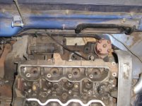
The top engine stabiliser bar is in the standard position. (to mate to a Beta head with threaded holes in the end) I fabricated the bracket to the head using plate steel and the original X19 top mount bracket. The original stay bar has been re-bushed with urethane at the motor end only.
I may still add in the Beta transmission mount as an extra attachment point, as I’ve traced a little give in the mounts to small gear shifting worry of mine..
The alternator is mounted on the exhaust side. I’m using for the moment, an exhaust manifold from a 124BC coupe. (Substantially bigger ports through the manifold fiat p/n 4151276) I have 38mm (1 ½”) diameter primary pipes from the manifold into a 63mm (2 ¼”) mandrel bend exhaust, using a custom made muffler, the tailpipe exits from the original location.
It has a remote oil filter and cooler. The oil leaves the engine from a custom made block that mounts to the usual filter block position, the filter and cooler are mounted where the carburettor cooling fan assembly once was. The oil returns into the engine at the front of the gallery that passes along the exhaust side. There is a direct feed to all crank journals from here. This cuts out two 90-degree bends inside the engine and gives better oil feed to the front main journal. I have heard reports of X19 twin-cams spinning engine bearings due to oiling problems, I think it’s because the oil would be getting too hot. I’ve built a few powerful Lancia Beta’s in my time, and never encountered and oiling problem, but the hard drivers always get oil coolers installed. I’ve helped prepared front drive twin-cams for racing, never had a problem, have always used an oil cooler.
Water piping is stainless steel with only short rubber joiners under the car to the original steel pipes, the inlet to the pump faces the gearbox, rather like the metal bypass pipe on a sohc, it hooks downwards from the engine and passes under the sump near the cross-member. The top water pipe exits through the timing cover, (a cut down alloy 1608 one) turns to the front of the car then passes along the front of the engine running along the chassis rails and down, it has two rubber joiners, one near the engine and one underneath. The standard heater hoses connect up, and the original stainless steel header tank stays in its original location
Gearbox is standard Australian spec. Beta, except I have the short diff ratio ex USA 4.21:1. The clutch used is a Fitchel & Sachs, 215mm Lancia 2000. The slave cylinder is standard X/19 as is the slave cylinder hose. The clutch actuation arm has been modified to move the arm through about 90 degrees to the right place. It’s a hybrid of an X/19 5 speed arm and the Lancia’s
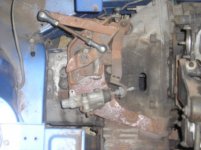
The shift linkage is my own design, I believe to be similar to a Montlecarlo/Scorpion, which I’ve never seen. I worked from pictures, parts books etc. The first parts of the linkage are standard ’78 X/19, up to the end of the steel shifter rod with two slotted holes in it… from there on it gets complicated to describe, but ill try….
From the gearbox end, and heading to the front….
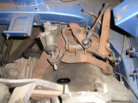
There is a linkage assembly mounted to a plate on top of the gearbox, using the (original Beta clutch cable support mounting) threaded holes that are in beta transmission.. An actuation rod pivots in a bush at the front of this plate to provide motion in the 1 to 2 plane. The lower pivot point for this rod is a small bracket on the bottom of the gearbox casing. Under a Beta box there is a circular raised casting, into this I drilled, tapped and fitted three M6x1 heli-coils into the alloy to mount this lower bracket.
A second rod is used to lift and lower (provides motion across the shift gate plane) the shifter stub which sticks out of the top of a Beta box (unlike a standard X19, which is at the front). It does this via a linkage assembly, which I modified from a 127 gearlinkage part, this is bolted to the top plate that I made. At its other end the second rod is mounted on a bracket bolted to the original shifter rod under the car, this provides the “up and down’ motion on the shifter stub to go across the gate. (when you go 2nd to 3rd etc) All the ends of the linkage rods, use small rod ends, these look like little tie rod ends complete with rubber boots. The shifter pivot inside the car is from a five-speed model.
It selects all 5 gears and reverse easily, but I’m a little disappointed with its slightly "springy" feel.
I’ve traced this to slight engine movement when shifting, like I said, I’m probably going to also fit the rear gearbox mounting from a Beta. It lines up pretty well with the transverse chassis member, If I weld a bracket in and use an original rubber mount which I have, this should hold that end of the assembly tight and the shifting should be more precise.
SteveC
These are some pictures I took a while ago, and have only recently developed and scanned. I will get more pics soon, as I will be removing the entire setup to copy for a T/C installation into the RacerX. (see other thread this X19 forum) I may even make up some jigs so I can replicate the setup for anyone keen on going the T/C option.
here is a (rather long) description of how I did it...
*Twin cam conversion*
It took a while to decide on the engines final position. I have taken utmost care to ensure the handling will not be unduly affected by the weight change. I figured that the front of a Lancia Beta is quite evenly weighted so I’d try to position the engine as it was originally, but only tilting it as much as I needed to get clearance for the carburettors. Tilting the engine too far back would shift the weight bias even further rearward. We don’t want that now, do we, so the engine/transmission assembly is mounted with only a 10-degree rearward tilt. I also spent a lot of time making sure the gearbox outputs were in line with the hub centres, so the axles would be absolutely straight when the car was running level.
Next step was to install the five-speed type hubs, front and rear, allowing me to use the larger wheel bearings. The later Ritmo/Uno type bearings last a lot longer at the front and the rears are now the same bearing as the Lancia Beta uses, so these are designed to support the increased weight. The later type hubs also gives you the drive flange at the rear instead of 128 style C.V. joints
The engine is positioned so the ends of the drive flanges of the gearbox (’m still using the Beta idle axle) are equidistant (exactly) If you don’t get the measurements right at this stage, the CV joints will bind at a point in the suspension travel. This allows me to use two standard short side 5 speed x19 axles to complete this part of the conversion, (neat huh), they match the Beta inner pattern and fit the std 5 speed rear hub. These are precisely in line with the drive flanges in both planes with the car sitting level, I have seen conversions with the axles skewed and the C.V. joints constantly running through a large angle, bad practice IMO.
As I said the bodywork only needed a small amount cut out to clear the transmission casing, from the left chassis rail, right about where the standard flex brake line mount is inside the wheel arch. I’ve had to move this bracket also, otherwise the brake rubber line will rub on the gearbox end casing. Also the alloy of the gearbox casing needs to be sculpted in a few places to provide a little extra clearance. You have to cut the body or the engine just won’t sit in the right place. I simply plated every thing up very neatly, making it all look very standard with lips in the right places. I also added some plating to the upper surfaces of the chassis-rail. I also gusseted it up where it connects to the forward engine bay transverse chassis member.
You do however, need to give a bit more clearance than the standard rear control arm will give to the gearbox. This involved cutting away, mostly from the upper part, sufficient material. I then boxed the arm, enclosing the open side. This should give it sufficient strength, but to be sure I added the amount I had cut from the inside edges of the arm back onto the outside of the arm as well.
The car uses a Fiat Regata 100s water pump. This is held to the engine block with 8 x 1.25 bolts and is cast iron. It has threaded holes for the cam-drive end engine mount. Mounted to these is a bracket I fabricated from plate and tube steel and pressed in the original rubber-mounting bush. It mounts to the original body bracket.
The lower cross-member uses the standard mounting points, the standard 8 x 1.25 10.9 grade bolts even. I cut a 128 cross-member up and used it to reinforce the original, it uses a different lower engine mounting. This consists of separate small “L” shaped bracket, one face of which bolts to the lower portion of the Beta bell housing, through existing holes. The other face of the bracket is on top of an early Holden (yes it fitted the best, that’s why I used it) transmission mounting. It’s just a plain rectangular block with two studs above (which I’ve recut to metric J) and a flat sturdy plate below, which bolts above the cross-member.
The top engine stabiliser bar is in the standard position. (to mate to a Beta head with threaded holes in the end) I fabricated the bracket to the head using plate steel and the original X19 top mount bracket. The original stay bar has been re-bushed with urethane at the motor end only.
I may still add in the Beta transmission mount as an extra attachment point, as I’ve traced a little give in the mounts to small gear shifting worry of mine..
The alternator is mounted on the exhaust side. I’m using for the moment, an exhaust manifold from a 124BC coupe. (Substantially bigger ports through the manifold fiat p/n 4151276) I have 38mm (1 ½”) diameter primary pipes from the manifold into a 63mm (2 ¼”) mandrel bend exhaust, using a custom made muffler, the tailpipe exits from the original location.
It has a remote oil filter and cooler. The oil leaves the engine from a custom made block that mounts to the usual filter block position, the filter and cooler are mounted where the carburettor cooling fan assembly once was. The oil returns into the engine at the front of the gallery that passes along the exhaust side. There is a direct feed to all crank journals from here. This cuts out two 90-degree bends inside the engine and gives better oil feed to the front main journal. I have heard reports of X19 twin-cams spinning engine bearings due to oiling problems, I think it’s because the oil would be getting too hot. I’ve built a few powerful Lancia Beta’s in my time, and never encountered and oiling problem, but the hard drivers always get oil coolers installed. I’ve helped prepared front drive twin-cams for racing, never had a problem, have always used an oil cooler.
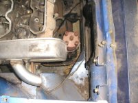
Water piping is stainless steel with only short rubber joiners under the car to the original steel pipes, the inlet to the pump faces the gearbox, rather like the metal bypass pipe on a sohc, it hooks downwards from the engine and passes under the sump near the cross-member. The top water pipe exits through the timing cover, (a cut down alloy 1608 one) turns to the front of the car then passes along the front of the engine running along the chassis rails and down, it has two rubber joiners, one near the engine and one underneath. The standard heater hoses connect up, and the original stainless steel header tank stays in its original location
Gearbox is standard Australian spec. Beta, except I have the short diff ratio ex USA 4.21:1. The clutch used is a Fitchel & Sachs, 215mm Lancia 2000. The slave cylinder is standard X/19 as is the slave cylinder hose. The clutch actuation arm has been modified to move the arm through about 90 degrees to the right place. It’s a hybrid of an X/19 5 speed arm and the Lancia’s
The shift linkage is my own design, I believe to be similar to a Montlecarlo/Scorpion, which I’ve never seen. I worked from pictures, parts books etc. The first parts of the linkage are standard ’78 X/19, up to the end of the steel shifter rod with two slotted holes in it… from there on it gets complicated to describe, but ill try….
From the gearbox end, and heading to the front….
There is a linkage assembly mounted to a plate on top of the gearbox, using the (original Beta clutch cable support mounting) threaded holes that are in beta transmission.. An actuation rod pivots in a bush at the front of this plate to provide motion in the 1 to 2 plane. The lower pivot point for this rod is a small bracket on the bottom of the gearbox casing. Under a Beta box there is a circular raised casting, into this I drilled, tapped and fitted three M6x1 heli-coils into the alloy to mount this lower bracket.
A second rod is used to lift and lower (provides motion across the shift gate plane) the shifter stub which sticks out of the top of a Beta box (unlike a standard X19, which is at the front). It does this via a linkage assembly, which I modified from a 127 gearlinkage part, this is bolted to the top plate that I made. At its other end the second rod is mounted on a bracket bolted to the original shifter rod under the car, this provides the “up and down’ motion on the shifter stub to go across the gate. (when you go 2nd to 3rd etc) All the ends of the linkage rods, use small rod ends, these look like little tie rod ends complete with rubber boots. The shifter pivot inside the car is from a five-speed model.
It selects all 5 gears and reverse easily, but I’m a little disappointed with its slightly "springy" feel.
I’ve traced this to slight engine movement when shifting, like I said, I’m probably going to also fit the rear gearbox mounting from a Beta. It lines up pretty well with the transverse chassis member, If I weld a bracket in and use an original rubber mount which I have, this should hold that end of the assembly tight and the shifting should be more precise.
SteveC
 You deserve some reputation for this