Technical Megasquirt

Currently reading:
Technical Megasquirt

Re: Megasquirt iac v3

This diagram is showing wiring connections on a V3 board, including MS-2 connections for IAC motor (4 wires, blue & green on top left) and ignition module (pink wire at 36 pin).

If MS-1 is used, these pins stay disconnected. Use pin 30 to control a simple two-pin idle valve.

Not reading enough I guess.

From the megasuirt manual for v3 megasquirt 1. my bold
quote
Idle Control valves

As long as the MS ECU has been upgraded internally (see the main MSnS Extra Hardware Manual) with a high powered transistor (the upgraded TIP122 transistor is fitted as standard by ExtraEFI.co.uk) in place of the standard idle transistor it can control most idle valves as long as they are NOT stepper motors (these have 4 wires/connectors) Most 2 or 3 wire valves (e.g. Bosch 0280 140 505)

unquote

Time for a rethink.
 
Ok, i was talking with Bill Shurvinton, an official UK Megasquirt supplier. I intent to place the Megasquirt under the passenger dash and drive the wires inside the engine compartment. Wires will enter an empty Marelli ECU box that i have and connect to the back of the male connector. This way i keep original harness intact.

Now, if we want to use the extra features megasquirt offers (like boost control, knock sensor, EGT etc), we need to use an extension board with various components, relays and connectors. This can be installed under MS case, inside the car and drive wires to the engine compartment, or fabricate a custom board to fit inside the Marelli box and solder on it the male connector too. This way we will have all connections and relays inside the dummy ECU, with easy access to the sensors.

Custom expansion board will cost around 35£, but Bill will only produce it if we order at least a dozen of them.

This board, will fit all 37pin Marelli ECU's, so Punto60-75-85, Alfa33, Cinque and Sei's are all compatible with it.

I'm interested, so anyone else who also does, leave a message.

megasquirt board group buy @ £35

asteris
 
Last edited by a moderator:
sounds like you've confsed two things there..

the relay board which can be mounted in the engine bay, and has all the sensor wires etc run to it is this thing in the right side of my engine bay

bay_01_03_07.jpg


there is then a 37pin cable that runs from it to the MS ecu which is under the dash.

the board made by Bill which adds all the extra features is this, on the right which sits in the top of the MS case

ecu_open.jpg


can you ask him if he can make some of these circuits up - http://www.msextra.com/viewtopic.php?t=18971

and also if when adding the knock input, do we still need a knock conditioning circuit like knocksense - or does his board have a filtered circuit.
 
Centos already have all relays needed for ignition, injectors, fuel pump etc, what's the point of scraping them and use the MS relay board?

Bill and me were talking about a single board inside a dummy ECU in the engine compartment, that will carry all sensor connections plus extra wires needed for non existing ones, like knock sensor, second injector bank etc. This board will be custom designed, so the male connector of the dummy ECU will be soldered directly on it. This way, all existing sensors will just plug to the dummy ECU using the female plug of the existing harness .

It's simply a matter of priorities. I do not intent to butcher my harness like you did, i might have to sell the car some day, or just return it to 1108 original state for my wife to use it on a daily basis.
 
ok, fyi i have a spare loom if i ever wanted to get the car to a sellable state (i don't plan to sell it mind)

i still don't 100% get what you mean re the board inside the old ECU casing.. not sure where you're going to get a connector for doing that.. and you're gonna butcher an ECU casing to make it all fit?

The MS ECU needs to go inside the car doesn't it? So all this board you are saying is about is going to be a relay board without the relays, that goes inside the old ECU case - it will still need the link to the main ECU in the passenger side.

With regards to adding the extra sensors.. if you're going to leave the stock loom as it is.. how are you going to add the wires for the knock sensor, extra injectors etc.. solder them to the stock ECU connector?

A word of warning, i was waiting around 6 months for my ECU after i paid for it..
 
MS will be installed under dash, that's for sure. Dummy ECU casing and connector (got a broken one from a car electrician for free) where original ECU was. A db37 cable for main connections plus one more for expansion will be driven from MS to dummy ECU. Original harness female connector plugs on the ECU as usual and connects all sensors that the car already has. Another connector is fitted on the ECU casing, that will connect all extra sensors like EGT, knock sensor and rest.

Inside the dummy ECU, instead of soldering wires to the back of the male plug, a custom board that Bill will design, will be soldered direct on the connectors (just like the original ECU board).

So, dummy ECU will have 4 connectors, original harness male connector, DB37 to the MS, another DB for extra wires to the MS and a DB9 for extra sensors to the engine.
 
Re: Megasquirt iac v3

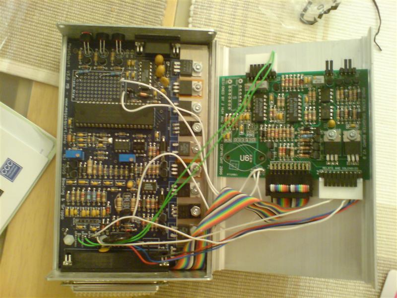
MS one cannot control a stepper motor idle control system.

i'm not sure why its shown connected like that, however it cannot work how its connected. the idle stepper motor would need 4 connections, not just that one.

Think I'll find a throttle body that uses pwm or a three wired bosch. Seems easier than sodding around with extra boards....could well be cheaper.

Or is that a backwards answer?

And yeah I'm wiring to an ecu, pull the guts, solder then plug it and play ...or not!

Bill Shurviton, who supplied my unit recommended this route. Build and delivery 2 weeks, not bad.

Butcher an ecu, mine was £9 delivered from ebay. What else are they to be used for?
Arc like your loom tidy - where'd it come from?

Hey why not use a Bosch icv - before tb and after with hose, plug in and use msquirt to control? block stepper icv off?
 
Last edited:
this might no make too much sence but im learning i think:confused:

i was thinking to retain the original loom/ecu plug(to return to stock if i needed) using a sort of dummy Weber/Mareli ecu with a custom pcb from
that going into a relay board then to the MS ecu.

my idea is to run throttle bodies so i would need a to make a new injection loom going in to the pcb in the
dummy ecu-relay board-MS ecu

thanks for any reply

also where have people been buying there MegaSquirt from?
 
:eek: sorry missed that

asteris i would be interested

megasquirt board group buy @ £35

Mine came from Bill Sh........ bum forgot.
I'm starting to link the megasquirt to a 'vandalised' ecu (god that was fun!)
I'll be putting the update on tomorrow pm. Punto/tech/supercharged together with Bill's address, yes I have asked him if its ok :)

Its hard work and I can now see why arc chose the relay board route.

the vandalised ecu route should work.....but, I feel very insecure as many relays etc are still unknown - it feels like, It should work but....

the relay board route (imho) has a much greater chance of success because its all contained and correctly (we hope) linked it looks like, I've put this together I know what goes where and if its wrong I can fix it...

Maybe not :shrugs: :chin:
 
:worship:
This request appears in 2 places as I am aware the it is quite technical. I'll copy responses across - thus duplicating but, in disparate areas (y)
Someone to check my ideas please, and correct them if wrong.

I'm sure other people will start using Msquirt when the wiring is sorted and we have a base map Rich Cinq is using it already!

First section - what I think......

followed by 2 wiring diagrams...


-------------------------------------------------------------------


Hi


This is how I have worked out he megasquirt to punto loom.

Is there an expert sparks who can check it for me:worship:

Will help future megasquirters no end.

Ignore the light green and light blue wires on stepper ICT as these only apply to the mk2 megasquirt with a v3 board. I’m using a Mk1 with v3 board and 29v firmware. This utilises pin 36 and pin 31 for coils.

Wiring for a v3 megasquirt board – with wasted spark upgrade using pin 36 for coil A and pin 31 for coil B.

I think..

Mega punto ecu connector

Pin 20 > pin 31 intake air temp sensor

Pin 21 > pin 13 coolant temp sensor

Pin 22 > pin 30 throttle potentiometer (?uncertain on this)

Pin 23 > pin 29 ( could be pin 12 but I think thats an earth?) lambda

Pin 24 > pin 11 (or should this be pin 28? Tach. crank take off, tdc.)

Pin 25 ignore

Pin 26 > pin 14 (please check?)

Pin 27 ignore

Pin 28 > pin 26 link to pin 14 to give + out to injectors

Pin 29 ignore

Pin 30 > relay for Fidle (no direct correspondence but could connect to stepper wiring which will be connected to a bosch or pwm idle valve?)

Pin 31 > pin 1 (coil b?) This is the wasted spark upgrade out. Not shown on v3 standard diagram.

Pin 32 , 33, 34, 35 > pin 18 injectors

Pin 36 > pin 19 (coil a?)

Pin 37 > pin 26 (live in on spi but not on sporting so sporting would need this added to car loom?)


Mega punto ecu connector


Pins 1 through to 6 ignore

Pin 7 > pin 28 (or should this be 11?) tdc tacho sensor


Pin 8,9,10,11 and 19 to > pins 17 and 16 bridged


Pins 12 to 18 ignore


Phew
If anyone can help me with this I would be very grateful – I’ll even pay !


I have included v3 wiring diagram and a punto diagram. I’m working from the Haynes diagram

-------------------------------------------------------------------


And


Thanks:worship: :worship: :D
 
this *may* help out. seeing as though the punto uses the same ECU. but this is all relevant to my car (1995 Cinq Sporting); don't know how it lines up with the punto.

fuel pump > orange and green
comes out as a green and black wire on the pump, the other connection on the pump is grounded (via the fuel cut off switch i beleive)

coil pack > blue and red
coil pack > white and green
coil power> light blue and green (wire to ign live)
The ECU triggers the coil packs with a negative pulse. The first two cables are these trigger cables, the coil power cable is a common wire between the two coil packs and should be wired to an ignition live cable. There is a 'spare' one in the ECU loom. It is orange. (or you can use the orange and black one; same thing)

tps vref > light blue and black
tps > pink
tps ret > black
Throttle posistion sensor wiring. The TPS Ret / Ground is a black cable, all the sensor earths are joined in the loom near the ECU. I remove this join as the Megasquirt has seperate inputs for the returns (helps eliminate ground loops). You will need to trace the return using a multimeter to check you have the TPS one. It's easy enough to do. TPS Vref should be supplied with a 5v reference voltage, your ECU should provide this. The TPS actually has two returns. One is wrapped around the blue/black VREF cable. I left this in place, and connected it to the other TPS ret just before it went into the ECU. I can only imagine its done like this for crosstalk issues.

tach/tdc > black and yellow
TDC wiring is found in the big thick red cable that looks like it should be a high current power cable. It is a sheilded cable, with two signal cores. The black and yellow cable is the positive, the blue and red is the negative. Negative on most systems can be connected to ground. There is a thin black wire that goes into the edge of the TDC cable, it is the ground for the sheilding. Make sure this remains connected to ground.

IAT > purple
CTS > purple and white
Inlet Air Temp and Coolant Temp Sensor signal wires. With the returns on them, same deal as the TPS return cable. They are both plain black wires and so will need a quick trace with the multimeter.

ign live > orange
live > red
grounds > black
Orange wire goes live when the ignition is switched on. Red wire is fed from the battery / loom. Origonally the red wire had the main fuses and fuel injection relay etc on it, but i don't need them so have removed them. If you are leaving them on, then you need the wire that goes to pin35 of the stock ECU which is brown with a white stripe.

idle control
phase A > dark blue and white
phase B > green

phase C > white
phase D > dark blue and yellow

Cable colours for the Idle Control Valve. It is a stepper motor type, bipolar.

MAP sensor.
Signal > Yellow and red.

Lambda
Signal + > dark blue with a yellow stripe
Signal - > brown with green stripe
Again the lambda cable is sheilded, in a green sheath. The other connections from it go to ground, or the main fuel injection relay to supply power for the heater.
 
Ok, soldering my V3 kit and a little bit confused. Our rev sensor is a hall sensor, isn't it?

So we need to solder step 50a and jumper what is mentioned at blue rectangle at step 52, right?
 
Ok, soldering my V3 kit and a little bit confused. Our rev sensor is a hall sensor, isn't it?

I thought (and the tech docs. back up) that it was a Variable Reluctance one.

I dunno if that follows the exact same principle as the Hall sensor as it seems Hall sensors go off magnets, and I dont think the crank wheel is magnetized :D
 
Update on Punto fitting:
Firstly, Bill's just let me know that the stepper board to convert pwm to control appears to be working, he's letting me know the price.
Secondly, I'm trying to sort my wiring and come up with a 'standard' for mk1 puntos. We (Bill and I,well mainly Bill :)
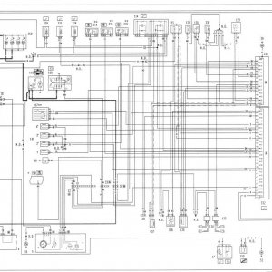
)should have a working diagram by the end of this week. Obviously, it might not happen, also it won't fit centos. It will provide a guide for use with fire engines using the relevant wiring diagram. I'm only posting this in case anyone else is struggling (as I am) to get this right first time, an answer might be available soon.
 
Last edited:
if you could get me one of them idle control boards, that'd be handy.

can you get confirmation on how the TDC sensor is wired. Looking at the FIAT specs, the TDC has a signal + and a signal -. can you confirm with Bill about if the signal - is to be tied to ground, or to pin7.
 
Back
Top