Technical Injector Waveform Picoscope

Currently reading:
Technical Injector Waveform Picoscope

Joined
Nov 18, 2020
Messages
999
Points
308
Location
Northamptonshire
On a previous thread someone mentioned the use of an occiloscope in Auto diagnostics.
Well i have a ducato and MES tells me the injector variances are greater than the FIAT spec of +-2 but under what conditions. So Ive watched a lot of you tube and bought a scope and an amp clamp probe.
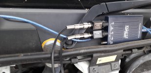
20230706_pico.jpg20230706_Clamp.jpg
The picoscope is attached to laptop via USB. The injectors are back probed.
The 3 samples here are from injector 1 at idle and 2000rpm
They are presented as is.
Please tell me what they show and what are the important bits to measure both on these and what differences between cylindars. They are obviously complex piezoelectric injectors. Any body have a clue? If someone turned up at my door with a perfectly running van i will be happy to take some golden samples.
inj1V2.png

inj1-VA1.png

inj1-VA2000rpm.png
 
On a previous thread someone mentioned the use of an occiloscope in Auto diagnostics.
Well i have a ducato and MES tells me the injector variances are greater than the FIAT spec of +-2 but under what conditions. So Ive watched a lot of you tube and bought a scope and an amp clamp probe.
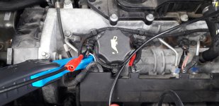
View attachment 426593View attachment 426592
The picoscope is attached to laptop via USB. The injectors are back probed.
The 3 samples here are from injector 1 at idle and 2000rpm
They are presented as is.
Please tell me what they show and what are the important bits to measure both on these and what differences between cylindars. They are obviously complex piezoelectric injectors. Any body have a clue? If someone turned up at my door with a perfectly running van i will be happy to take some golden samples.
View attachment 426594
View attachment 426595
View attachment 426596
A shame you can't scope all 4 injectors at the same time to view the true difference period wise between them.

So if variance is adjusted at idle do you need to measure at 2000rpm? That's just a question, I have little knowledge of this.

Which model Picoscope did you buy?
 
I do not think that I can offer much help, but would it be possible to monitor two injector voltage traces, instead of using the current probe. This would enable comparisons to be made between two injectors. From previous reading I have the impression, which could be incorrect, that the ECU uses two injector power circuits. Logic says that such circuits would be shared to alternate injectors, according to firing sequence which will probably be 1-3-4-2.. Hence if injestors 1 & 4 are monitored any other differences should be excluded. Then repeat with injectors 2 & 3.

When all four voltage traces have been taken, then examine for differences in voltage waveforms, and compare any injector showing differences with others in more detail.

I am probably preaching to the converted, but for the benefit of others, a piezo electric device is a capacitor which absorbs electrical energy by distorting its molecular structure. When a pulse of electrical energy is applied the current rises steeply, while the change of voltage lags behind. Put another way the current leads the voltage. This is clearly shown on the traces provided.
 
A shame you can't scope all 4 injectors at the same time to view the true difference period wise between them.

So if variance is adjusted at idle do you need to measure at 2000rpm? That's just a question, I have little knowledge of this.

Which model Picoscope did you buy?
All budget end of game
Picoscope 2204A (no probes) (cheaper available but picoscope software regarded best and plenty of support (except for Diesel injectors):)
Clamp Hantek cc65
hantek automotive probe leads
hantek aligator/dolfin clips (big crock clips bannana fitting)
hantek attenuators 20x HT201 needed to read voltages greater than 20V (or you fry the scope)

As to other questions
Don't know
i just measured at 2000RPM just to see if there was a change.
I also have the same for cylinders 1,2,3,4 at idle (except for current on 4, because a lot of dismantling would be required)
It is possible to measure all sorts just don't know what is relevant. I will have a play and put some stuff up for comment
any accepted except why and "what a waste of time".

why is easy: to get sensible answers from somebody
 
Its been trying to rain all afternoon and i don't want to be doing this in the rain so i got some numbers from whats already done. they are in the notes section at bottom of pictures. I didnt go about it in a very regorous way I was just playing so surprised with what I saw . unlike anything online (eg current 18A most ive seen was 8A petrol typicaly 1A. if there are any examples you've seen let me know.
inj3-1-V.png

inj3-2-A.png

inj3-2-B.png

inj4-B.png

inj 4 2nd.png


injector.png


this is the MES description for injector pids. duration and advance are also included
 
Its been trying to rain all afternoon and i don't want to be doing this in the rain so i got some numbers from whats already done. they are in the notes section at bottom of pictures. I didnt go about it in a very regorous way I was just playing so surprised with what I saw . unlike anything online (eg current 18A most ive seen was 8A petrol typicaly 1A. if there are any examples you've seen let me know.View attachment 426611
View attachment 426612
View attachment 426613
View attachment 426614
View attachment 426615

View attachment 426616

this is the MES description for injector pids. duration and advance are also included

What does MES say your injector correction is?

I would be interested to see individual injector timings at idle, just like graph one above but at a different timebase so we can see the five individual pulses to each injector.
 
Back
Top