Hi everyone,
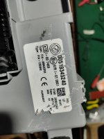
I’m working on a Fiat Panda 312 BCM (Body Control Module) that’s presenting some issues. The daytime running lights (DRL) are not working, and neither are the rear brake lights (the two 21W bulbs). However, the third brake light (the center high-mounted one) works perfectly.
In diagnostic, the only fault codes I see are related to the front DRLs – nothing else.
What’s strange is that both main rear brake lights are not working, yet the third brake light is. This makes me suspect a hardware issue inside the BCM.
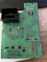
After opening the BCM, I found a damaged high-side switch (not exactly a MOSFET, more like a smart switch). There was a visible crack underneath the component, and the output pins were purple, clearly overheated. Unfortunately, there are no designators on the PCB to identify it.
I've removed the component and confirmed that the outputs were shorted to 12V, which might explain why the DRLs stayed permanently ON before removal – likely a short to battery. Even after desoldering the component, the output pads are still shorted to 12V, which seems very odd.
Has anyone experienced something similar?
Does anyone have a schematic or BCM pinout for this module?
I’m fairly confident that this component controls the DRLs, because now, with it removed, the DRLs no longer turn on. I’ve also managed to source a replacement BCM from another vehicle, but I’m not sure how to bypass or remove the immobilizer in order to test it.
Any help, advice, or shared experience would be really appreciated. I’ll attach some photos of the damaged component below.
Thanks in advance!
I’m working on a Fiat Panda 312 BCM (Body Control Module) that’s presenting some issues. The daytime running lights (DRL) are not working, and neither are the rear brake lights (the two 21W bulbs). However, the third brake light (the center high-mounted one) works perfectly.
In diagnostic, the only fault codes I see are related to the front DRLs – nothing else.
What’s strange is that both main rear brake lights are not working, yet the third brake light is. This makes me suspect a hardware issue inside the BCM.
After opening the BCM, I found a damaged high-side switch (not exactly a MOSFET, more like a smart switch). There was a visible crack underneath the component, and the output pins were purple, clearly overheated. Unfortunately, there are no designators on the PCB to identify it.
I've removed the component and confirmed that the outputs were shorted to 12V, which might explain why the DRLs stayed permanently ON before removal – likely a short to battery. Even after desoldering the component, the output pads are still shorted to 12V, which seems very odd.
Has anyone experienced something similar?
Does anyone have a schematic or BCM pinout for this module?
I’m fairly confident that this component controls the DRLs, because now, with it removed, the DRLs no longer turn on. I’ve also managed to source a replacement BCM from another vehicle, but I’m not sure how to bypass or remove the immobilizer in order to test it.
Any help, advice, or shared experience would be really appreciated. I’ll attach some photos of the damaged component below.
Thanks in advance!