Tuning Canterbury 695

Currently reading:
Tuning Canterbury 695

Trouble is, if there was enough damage to cause movement in the front x member and this was not repaired properly before replacing the outer panels then if it goes on a jig and pull the x member into place, all your external panels may move, distort or need replacing.
This could work out rather costly.
There maybe an easier option of cutting the section out of the inner arch which mounts the suspension arms and moving it forward a few mm to increase the wheel base. The only thing is this could effect the caster angle if the 2 studs in the x member are in the wrong place. So these may need to be cut and welded as well.
Stocks of Canterbury just on the other side of the fence from the tip might be able to help. But they would probably want it with the suspension and interior removed. If you went there and spoke to Keith or Clive and tell them I sent you (Sean Thomas from Direct Line) they may assist you.
 
Many thanks Sean
I am replacing the front panel, wings and inner (outer part) wings as part of the painting
I'm fitting bolt on arches at the same time - so not concerned about the damage caused by straightening
I will speak to the body shop who will be carrying out these works and see if it's something they can undertake
 
Completed the rear disc fitting today and have a solution to the handbrake cable - so onwards we march
 
Possibly, but it all depends on if the lower studs in the x member are in the correct position otherwise it will affect the castor angle and your car could end handling like a shopping trolley
 
Been considering how to measure these
Problem as I see it is that I only have a flimsy front panel to reference left to right and its been changed probably as part or the original accident
How could I check for trueness? - it will probably be out by 10mm at most
 
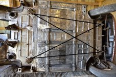
Andrew, you could get a (preferably new) steel tape-measure and measure the distance between one of the front leaf-spring mounting studs on each side and a fixed point, such as the centre of the pivot-bolt of the swinging-arm at the corresponding side at the rear. Obviously these measurements will be identical in a perfect setup.
If you could also get a diagonal measurement from front offside to rear nearside and vice-versa and see how close these measurements are, you would get an idea just how far out things are out.
Quite tricky to do this with any confidence in the measurements, but builders do that when trying to square up a footing for asimple structure.
Sean might be able to get an idea of what those measurements should be from the frame he made to support Franko when he was in bits.
_JAN2667 by Peter Thompson, on Flickr
 
If you have a very flat area of concrete, raise the vehicle up on axle stands to an even height side to side.
Then you can attach a plumb weight from set points and make a mark on the concrete. then measure the distance from these points.
Its not totally accurate but it should help point out where your problem lies.


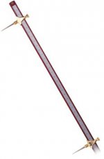
Ideally either buy or make an adjustable trammel guage to measure the distance. As long as the distances are about the same each side the vehicle should drive straight as the wheel alignment and steering geometry was not as critical as modern cars.
 

Attachments

  • 27307547421_415100f1df_c.jpg
    27307547421_415100f1df_c.jpg
    222.2 KB · Views: 37
  • pt-1_image.jpg
    pt-1_image.jpg
    8.1 KB · Views: 34
The technique Sean mentions is pretty accurate for a rudimentary check. I did this once on one of my land rovers. I used a punch as a plumb weight and fishing line. That helped to make accurate marks with a marker pen. Mine showed that mine was out by about 1 1/2" on one side, and had actually been manufactured like that! ;)
 
Well I'd better get measuring!
Thanks to all of my forum friends - I will update ASAP
 
Very interesting problem that you have Andrew, which I am following closely. The reason?--my N/S is also out of alignment compared to the O/S. I have measured and my wheel base is about 6mm shorter on the N/S. This doesn't sound a lot, but like on your car, it pulls the tyre back, and very close to, the back of the wing aperture. My problem is heightened by the fact that whoever repaired the car in the past also fitted the front spring stud panel 8mm across to the left! Has made for some interesting fettling. One dodge that I did (as a temporary 'fix' as it is going to be investigated properly over next winter) was to file the BACK of the spring bush (or push it through further) until the central metal tube was flush with the edge of the back edge of the main leaf, and then fit shimming washers to the FRONT of the spring between the spring and the king-pin carrier leg. I then fitted the matching thickness of washers to between the BACK of the top king-pin carrier bush and the rear wishbone. This effectively moved the whole king-pin carrier forward a bit, just enough to stop hitting the rear of the wing aperture---worth a try and it costs almost nothing.
banghead.gif
banghead.gif
cry.gif
smile.gif
 
Hi Tom


The only difference to your "adjustment" is that I now run a steel framed independent front suspension setup
Moving the two stud mounts on the problem side would be interesting.
I was hoping that just moving camber pivot arm forward 10mm will not upset the bottom connection of the kingpin.............
 
If the wheel on one side has been pushed backwards, I would expect the wheel on the other side been pivoted forwards slightly by the torsion of the spring on a car with the leafspring. If so, that would be an advantage if you were simply trying to equalise the wheelbase each side because an adjustment in the right direction on one side should also make small difference on the other, meaning that a relatively small movement will have an bigger effect towards evening-out the wheelbases.

So hypothetically, although I don't know if there is enough metal in the components to allow it to be done safely, but could you oval out the two holes where the top suspension pivot bar locates on the wheelarch studs and do the same in the aluminium blocks where the spring sits?

Then the kingpin assemby could be moved uniformly forwards or even deliberately inclined to get the castor you require.
 
Good thinking Peter. I had a good look at trying to modify the aluminium spring-mounting blocks, so as to try and move them forward/backward as required. The amount 'gainable' is minimal, only about 1/16, and quite a lot of work is involved to achieve even this. I did this as well as the fettling with the spring/kingpin carrier and just gained enough to allow me to drive without the tyre catching on the wheel arch.
My main job over the winter 2016/2017 is to sort this problem out properly. I have already started chatting with one of the local classic car restorers who has an idea how to achieve correct re-alignment---sadly I don't think that it will be cheap!
banghead.gif
cry.gif
smile.gif
 
With my new independent suspension setup - moving the main frame that mounts to the spring hangers is not going to happen
I'm drawn towards having some modified camber brackets fabricated (this work is FOC) and seeing what impact it has on the king pin mount at the base
I have some adjustments possible as ball joints are fitted here
 
Do I now have your approval Peter?
I'm sure you will love the rest of the works!
It is authentic- if the 500 was rallied.....
Engine - suspension- interior- rally clocks - wheels - hardtop
It's just my interpretation- purely for fun
 
Back
Top